BLOWER M OT OR SWI T CH
DESCRIPTION
The blower motor is contr olled by a thumbwheel-
type blower motor control, mounted in t he A/C-heater
control (Fig. 17). The switch a llows t he selection of
four blower motor speeds wit h the ignition switch in
the On position .
NOTE: The blower motor will operate only at the
lowest speed when the Residual Engine Heat Utili-
zation (REST) function is selected, regardless of the
blower speed setting on the A/C-heater control.
OPERATION
When the ign ition is turned t o On, th e integral
blower motor switch with in the ATC A/C-heater con-
trol su pplies power to th e blower m otor switch. Th e
switch directs power to t he individual blower dr iver
circuits throu gh the blower motor resistor block to
the blower m otor and t hen to ground.
The blower mot or swit ch can not be adjusted or
repaired, a nd if faulty or damaged, t he A/C-h eater
control mu st be replaced (Refer to 24 - HEATING &
AIR CONDITIONING/CONTROLS/A/C HEATE R
CONTROL - REMOVAL).
DI AGN OSI S AN D T EST I N G
BLOWER MOTOR SWITCH
The blower m otor switch can be diagnosed by u sing
the DRBIII! scan t ool. Refer to Body Dia gnostic Pro-
cedures. F or circuit descr iptions and diagram s, refer
to th e appropriate wiring infor mation.
EVAPORAT OR T EM PERAT U RE
SEN SOR
DESCRIPTION
The evaporator tempera ture sensor measures th e
temper ature of the condition ed air downstream of t he
A/C evaporator (Fig. 18). The evaporator tempera ture
sensor is an electrical thermistor within a molded
plastic ca se t hat is inserted into the HVAC h ousing
near the coldest point of the A/C evapora tor. Two ter-
minals wit hin the conn ector receptacle connect the
sensor to the vehicle electr ical system t hrough a wir e
lead a nd connect or of the HVAC wire har ness.
The external loca tion of the evapora tor tem pera-
ture sensor a llows th e sen sor to be rem oved or
insta lled with out distur bing the r efrigera nt in the
A/C system .
OPERATION
The evaporator t empera ture sensor m onitors the
temper ature of the A/C evaporator. The sensor will
change it s interna l resistance in respon se to the t em-
perat ures it monitors. The A/C-hea ter con trol is con-
nected to th e sensor th rough a sensor ground cir cuit
and a sen sor signa l circuit. As the evapora tor t em-
perat ure increases, t he resistan ce of t he sensor
decreases a nd th e volt age monitored by t he A/C-
heat er control decreases. Th e A/C-heater control uses
this monitor ed volta ge rea ding to an indication of th e
evapor ator tem perat ure. The A/C-heater control is
pr ogrammed to respond to this input by cycling the
A/C compressor clutch off if the evapor ator tempera -
ture sensor rea ds between 1° C (33° F) and 3.5° C
(38° F) to protect the A/C evaporator from freezing.
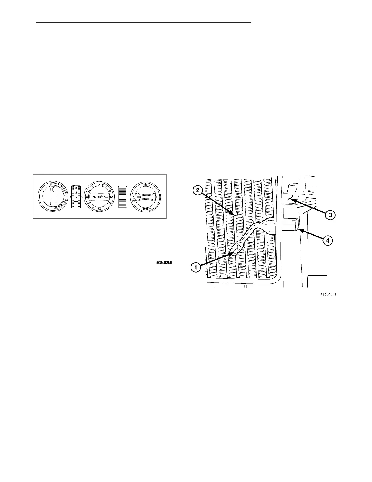
Fig. 17 A/C-Heater Control
Fig. 18 Sensor-Evaporator Temperature
1 - EVAPORATOR TEMPERATUE SENSOR
2 - A/C EVAPORATOR
3 - HVAC HOUSING
4 - WIRE CONNECTOR
VA CONTROLS-FRONT 24 - 19