The ext erna l location of the sensor allows the sensor
to be rem oved or inst alled with out disturbing the
refriger ant in the A/C system .
The evapora tor tempera ture sen sor is diagnosed by
performing the ATC Function Test u sing a DRBIII!
sca n tool. Refer to Body Dia gnostic Procedu res.
The evapor ator tempera ture sensor cannot be
adju st ed or repa ired and, if faulty or dam aged, it
must be r eplaced.
REMOVAL
(1) Disconn ect and isolate the negat ive ba tter y
cable.
(2) Remove the radio (Refer to 8 - ELE CTRICAL/
AUDIO/RADIO - REMOVAL).
(3) Remove glove com pa rtment.
(4) Remove cover fr om instrument clu st er (Refer t o
23 - BODY/INSTRUMENT PANE L/INSTRUMENT
PANEL TOP COVER - REMOVAL).
(5) Remove th e in st rument cluster (Refer to 8 -
ELECTRICAL/INSTRUME NT CLUSTER -
REMOVAL).
(6) Remove passenger side a irba g.
(7) Remove cover above air nozzle on pa ssen ger
side.
(8) Remove speaker.
(9) Remove cent er section of instr umen t pa nel.
(10) Remove A/C-hea ter cont rol from th e in st ru-
ment pa nel (Refer to 24 - HEATING & AIR CONDI-
TIONING/CONTROLS/A/C HEATER CONTROL -
REMOVAL).
(11) Remove in strument panel top sect ion.
(12) Remove electrical connection s.
(13) Remove air bezels from instrument pan el.
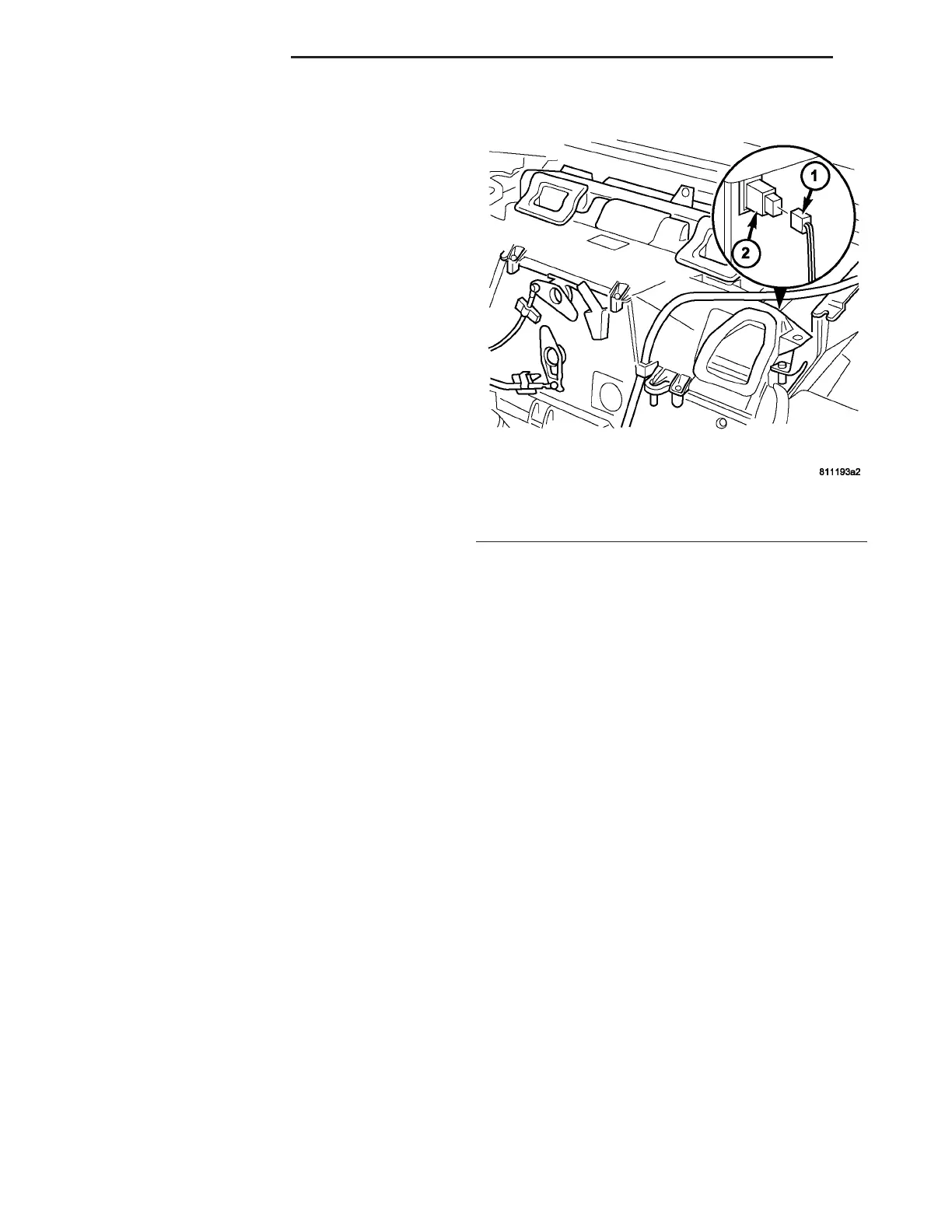
(14) Disconn ect the wire har ness connector from
evapor ator tempera ture sensor (Fig. 19).
(15) Remove evapora tor tem per ature sensor fr om
HVAC housin g.
INSTALLATION
(1) In st all the pr obe of the evapor ator t empera ture
sensor between the fins of t he A/C evaporator.
NOTE: The probe must not go into the same hole
(in the A/C evaporator ) that the probe was removed
from.
(2) In st all t he wir e h arness conn ector to the evap-
orator temperatur e sensor.
(3) In st all the air bezels to the in st rument panel.
(4) In st all the elect rica l connect ions.
(5) In st all the instr umen t panel t op section (Refer
to 23 - BODY/INSTRUMENT PANEL/INSTRUMENT
PANEL TOP COVER - INSTALLATION).
(6) In st all the A/C-h eater contr ol (Refer t o 24 -
HEATING & AIR CONDITIONING/CONTROLS/A/C
HEATER CONTROL - INSTALLATION).
(7) In st all the center section of the in st rumen t
panel.
(8) In st all the spea ker (Refer to 8 - ELECTRICAL/
AUDIO/SPEAKER - INSTALLATION).
(9) In st all t he cover above th e a ir nozzle on the
passenger side.
(10) Install the passenger side a irba g.
(11) In st all the instrument clu st er (Refer t o 8 -
ELECTRICAL/INSTRUME NT CLUSTER - INSTAL-
LATION).
(12) Install the cover t o the instrument cluster.
(13) Install glove compartment.
(14) Install t he radio (Refer to 8 - ELECTRICAL/
AUDIO/RADIO - INSTALLATION).
(15) Reconn ect the n egative battery cable.
Fig. 19 Evaporator Temperature Sensor
1 - WIRE HARNESS CONNECTOR
2 - EVAPORATOR TEMPERATURE SENSOR
24 - 20 CONTROLS-FRONT VA