IN - CAR TEMPERATURE SEN-
SOR
DESCRIPTION
The in-car t empera tur e sensor mea su res the actua l
air tem per ature with in t he pa ssen ger compart ment .
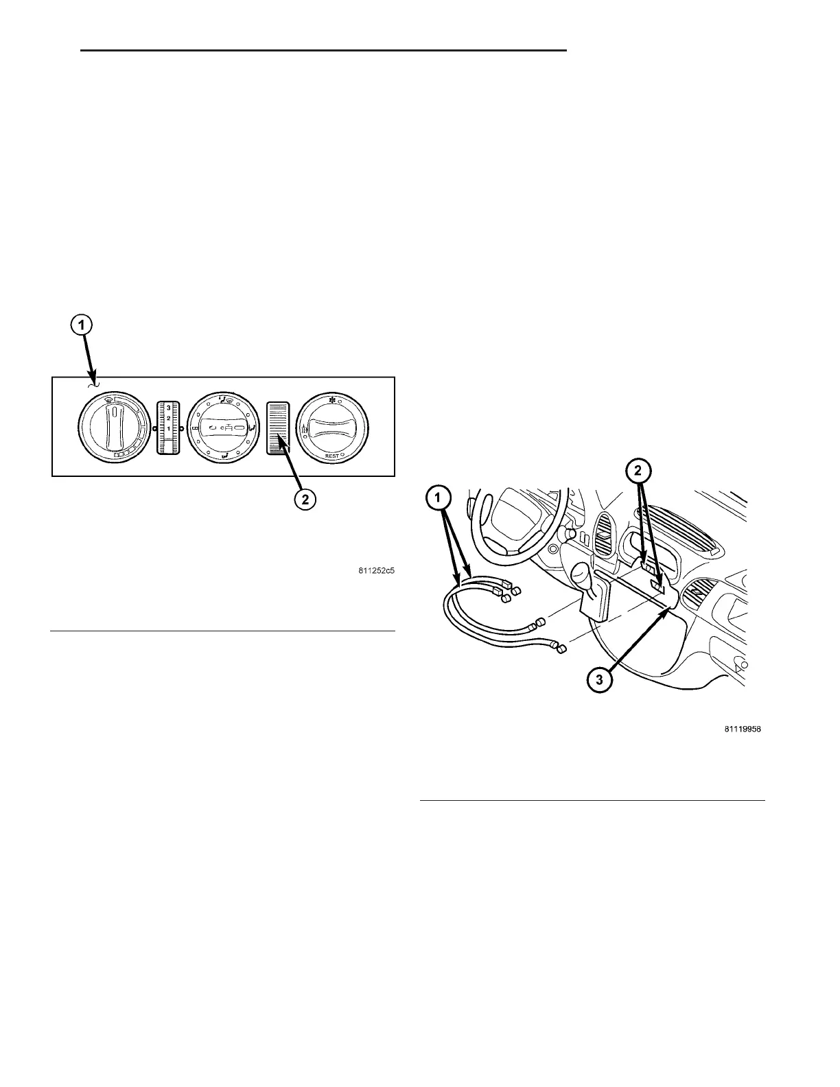
The in-ca r t empera ture sensor is locat ed in side of the
A/C-heater contr ol behind a vent ed pan el (Fig. 20)
and is n ot a sepa rate serviceable com pon ent. The
A/C-heater cont rol must be r eplaced if th ere is a fault
rela tin g to t he in-car tem perat ure sen sor.
OPERATION
Air from the pa ssen ger com pa rtmen t flows over the
ther mistor of the in-ca r tem perat ure sen sor. The
ther mistor changes r esistance with a ir temperature.
The ATC A/C-heater control measures this resist ance
and calculates the tempera ture of th e a ir. The A/C-
heat er control then makes adju st ment s to maintain
the selected pa ssen ger compa rtment tem perat ure.
The in-car temperatur e sen sor can not be a djusted
or repaired, an d if fault y or dama ged, the A/C-hea ter
control mu st be replaced (Refer to 24 - HEATING &
AIR CONDITIONING/CONTROLS/A/C HEATE R
CONTROL - REMOVAL).
DI AGN OSI S AN D T EST I N G
IN - CAR TEMPERATURE SENSOR
The in-ca r tem perat ure sensor is diagn osed by per-
forming t he ATC Function Test usin g th e DRBIII!
sca n tool. Refer to Body Diagnostic Pr ocedures. For
circuit description s a nd diagram s, refer t o the appro-
pr iate wiring infor mation.
MODE DOOR CABLES
REMOVAL
The air distribution cont rol cables (mode door
cables) can be removed a nd insta lled with out having
to remove the instrumen t pa nel fr om the vehicle.
(1) Disconn ect and isolate the negat ive ba tter y
cable.
(2) Remove t he center bezel from the instrument
pa nel (Refer to 23 - BODY/INSTRUMENT PANEL/
INSTRUMENT PANE L CE NTE R BEZEL -
REMOVAL).
(3) Remove t he A/C-heater cont rol (Refer to 24 -
HEATING & AIR CONDITIONING/CONTROLS/A/C
HEATER CONTROL - RE MOVAL).
(4) Mark and disconnect the con trol cables from
the A/C-heater contr ol.
(5) Mark and disconnect the con trol cables from
the H VAC housing ret ainer s (F ig. 21).
(6) Disconn ect the con trol cables from the m ode
door lever s and remove the cables from the vehicle.
INSTALLATION
(1) Connect t he two control cables to th e mode
door lever s (Fig. 22).
(2) Connect the two con trol cables to the A/C-
heat er control.
NOTE: Install the control cable of bottom adjust-
ment lever to the front adjustment wheel of the A/C-
heater control.
(3) Hold th e A/C-heat er control in it s insta lla tion
position .
Fig. 20 In-Car Temperature Sensor
1 - A/C-HEATER CONTROL
2 - IN-CAR TEMPERATURE SENSOR
Fig. 21 Air Distribution Control Cables
1 - AIR DISTRIBUTION CONTROL CABLES
2 - ADJUSTMENT LEVERS
3 - HVAC HOUSING
VA CONTROLS-FRONT 24 - 21