NOTE: While holding the A/C-heater control in the
installation position, verify that the control cables
are not twisted.
(4) Turn t he m ode control knob on the A/C-heater
control to t he nine-o-clock position .
(5) Turn the upper m ode door lever counter-clock-
wise until it reaches it s stop and install the cable
into the reta iner in this position (arr ow).
(6) Turn the lower mode door l ever clockwise until
it reaches its stop and install the ca ble into the
reta iner in this position (arr ow).
(7) Operat e t he mode con trol and ver ify th at th e
mode door cables are properly adjusted.
(8) In st all th e A/C-heater cont rol and the two
reta ining screws. Tigh ten t he screws to 2 N·m (17 in .
lbs.).
(9) In st all the center bezel onto the instrument
pa nel (Refer to 23 - BODY/INSTRUMENT PANEL/
INSTRUMENT PANEL CENTER BEZEL - INSTAL-
LATION).
(10) Reconn ect the n egative battery cable.
RECI RCU LAT I ON DOOR ACT U -
AT OR
DESCRIPTION
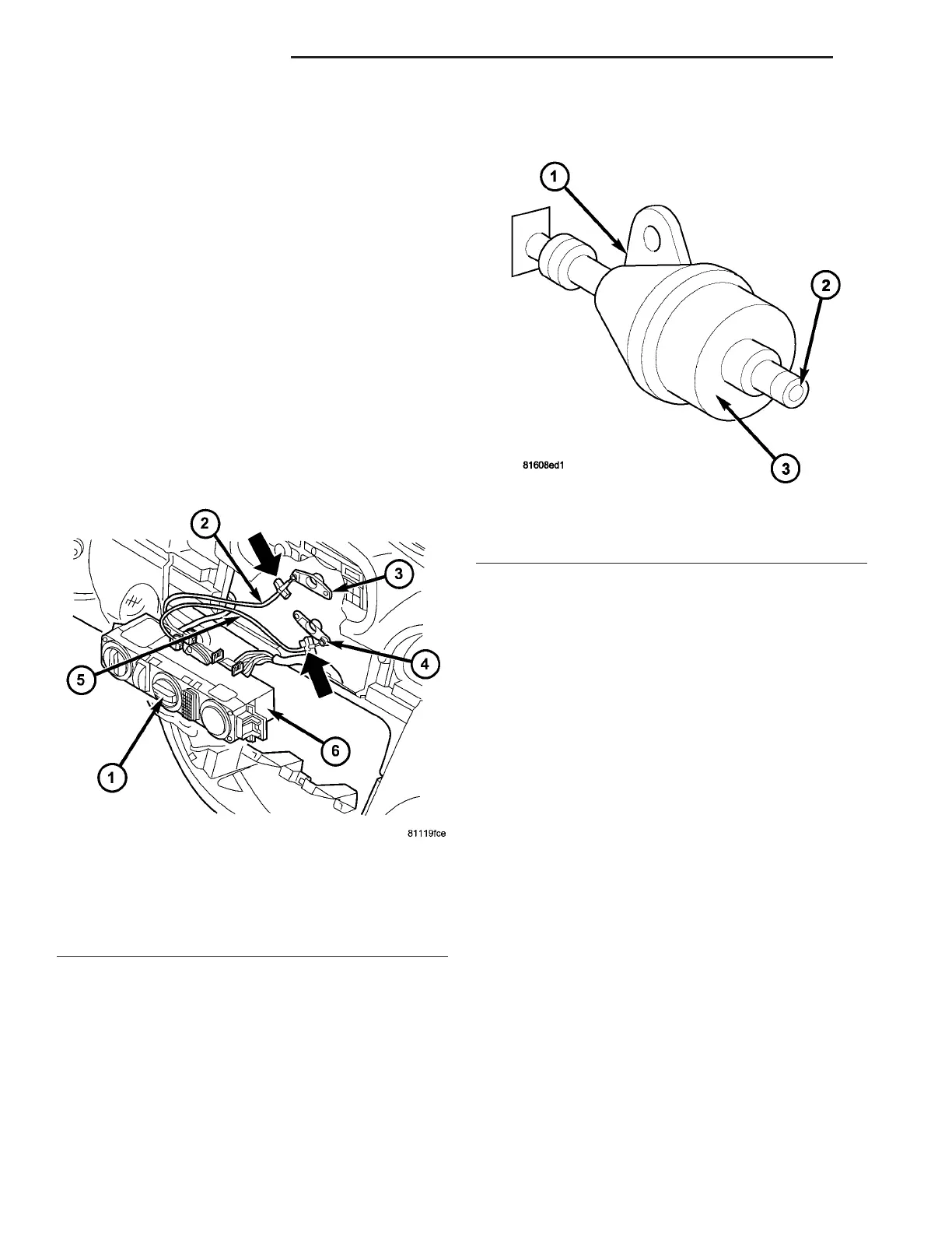
This vehicle uses a two-position va cuum opera ted
recir cula tion door actuat or to m ove t he r ecircu lat ion
door (Fig. 23). Va cuum supply to th e recirculation
door a ctuator is controlled by an int egra l electronic
control solenoid. The recirculat ion door actu ator is
mounted on the out board side of the ventilat ion
housin g above the blower motor in the engine com-
part ment .
OPERATION
The r ecircu lation door actuat or uses engine vac-
uum, wh ich is cont rolled by an in tegr al electrical
solenoid. Th e electrical solen oid is con nected to the
A/C-heater contr ol th rough the vehicle elect rical sys-
tem by a dedicat ed two-wire lead a nd connector. Th e
output shaft of the r ecircu lat ion door actua tor is
keyed to a pivot sha ft, wh ich is keyed t o the recircu-
lat ion door shaft. The recirculation door act uator can
move the r ecircu lat ion door in two directions.
The recirculation door a ctua tor is cont rolled by a n
electrical swit ch that is int egra l t o the A/C-heater
control. When the rot ary-type mode control is m oved
to the recir culation position, a signal is sen t t o the
electrical solenoid within th e recircu lat ion door
actuator. This signa l cau ses the solenoid t o open a
por t to engine vacuum which pulls the output shaft
into t he a ctua tor, which moves th e recircu lation-air
door. The a ctuator is spr ing loaded so the door moves
to the fresh-a ir position when no vacuu m is supplied
through th e elect rica l solen oid.
The recirculation door actu ator can be diagnosed
by performing the ATC Fu nction Test u sing a
DRBII I! sca n tool. Refer t o Body Dia gnostic Proce-
dures.
The recirculation door a ctuator can not be repa ired
and, if fau lty or da maged, it must be replaced.
REMOVAL
(1) Disconn ect and isolate the battery nega tive
cable.
Fig. 22 Adjusting Air Distribution Control Cables
1 - MODE CONTROL KNOB
2 - UPPER MODE DOOR CABLE
3 - UPPER MODE DOOR LEVER
4 - LOWER MODE DOOR LEVER
5 - LOWER MODE DOOR CABLE
6 - HEATER-A/C CONTROL
Fig. 23 Recirculation Door Actuator
1 - RECIRCULATION DOOR ACTUATOR
2 - VACUUM CONNECTOR
3 - ELECTRONIC CONTROL SOLENOID
24 - 22 CONTROLS-FRONT VA