INSTALLATION
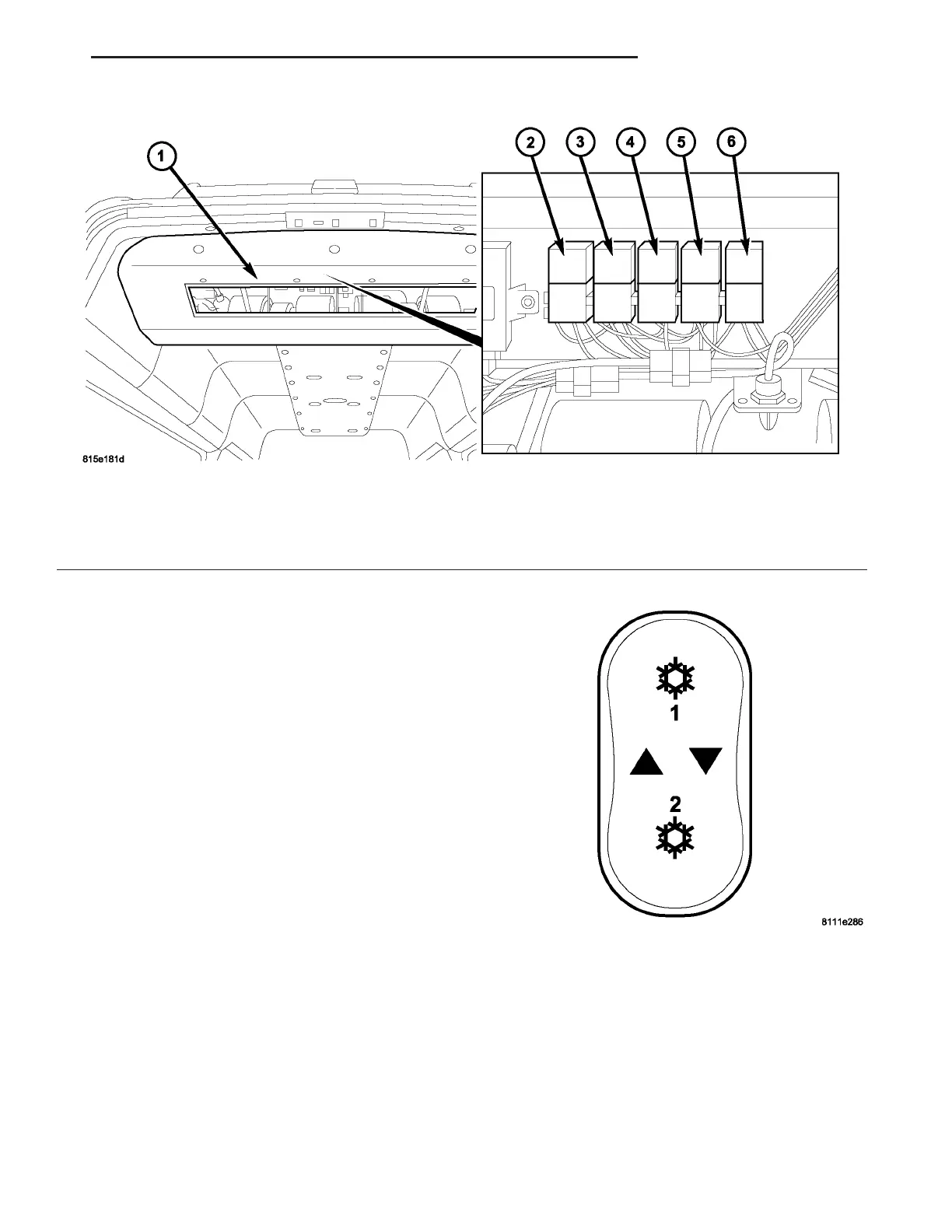
(1) Position the rea r blower motor relays into t he
pr oper receptacle of t he rela y block located in the
rear A/C eva por ator housing as necessary.
(2) Align the blower motor r elay terminals with
the ter minal cavities in th e relay block receptacle
and push down firmly on the r elay un til the termi-
nals are fully sea ted.
(3) In st all th e rea r air filter (Refer to 24 - HEAT-
ING & AIR CONDITIONING/DISTRIBUTION -
REAR/AIR FILTE R - INSTALLATION).
(4) Reconnect t he negat ive batt ery cable.
BLOWER M OT OR SWI T CH
DESCRIPTION
The blower mot or for the optional r ear A/C system
is con trolled by a th ree position r ocker switch
mounted in the swit ch panel located on t he instru-
ment pan el (Fig. 13). Th e rear A/C blower motor
switch allows th e selection of one of t wo blower
motor speeds an d a n Off position.
OPERATION
With the fron t A/C swit ch activat ed, the rear
blower motor speed can be selected by pressin g the
rocker switch upwards (high speed) or downwar ds
(low speed). To tu rn the rear blower motor off, switch
the blower motor switch to t he center position.
Depending on th e blower motor swit ch position, a
blower mot or speed com mand signal is sent to one of
the two blower m otor relays. When activa ted, relay 1
sends power throu gh a n in tegr al resistor within the
rear A/C cont rol module a nd then to the blower
Fig. 12 Rear Blower Motor Relays
1 - REAR A/C EVAPORATOR HOUSING
2 - BLOWER MOTOR RELAY K204
3 - BLOWER MOTOR RELAY K203
4 - BLOWER MOTOR RELAY K201
5 - REAR CONDENSER FAN RELAY K205
6 - REAR COMPRESSOR RELAY K206
Fig. 13 Rear Air Conditioning Switch
VA CONTROLS - REAR 24 - 35