INSTALLATION
(1) In st all th e rear A/C blower motor switch into
the accessor y switch pan el. Ma ke sur e th e ret aining
tabs a re fully engaged.
(2) Connect the wire harness connector to th e rear
A/C blower motor switch.
(3) In st all the accessory switch panel (Refer to 23 -
BODY/INSTRUMENT PANE L/ACCESSORY
SWITCH BEZE L - INSTALLATION).
(4) Reconnect t he negat ive batt ery cable.
EVAPORAT OR T EM PERAT U RE
SEN SOR
DESCRIPTION
The rear evapor ator t empera ture sen sor (Fig. 15) is
used to signa l the rear A/C control m odu le to cycle
the rea r A/C clu tch in order to control r ear evapor a-
tor temper ature. Con trolling the evaporator t empera -
ture prevents condensat ion on th e evapora tor fins
from freezing and obstru cting rea r A/C system air
flow.
The rear evaporator t empera ture sensor consist s of
a probe and a switch un it. The probe, which is a Neg-
ative Temper atur e Coefficient (NTC) ther mistor in a
capillar y tube, is inserted between th e rear evapora -
tor coil fin s to monitor evapora tor tempera ture. The
switch unit con tains interna l contr ol logic th at mon-
itors the in pu t fr om t he probe in or der t o switch an
internal t ransistor t hat controls the ou tput signa l to
the r ear A/C control module.
The rea r evapora tor temperature sen sor is located
in the rear A/C eva por ator housing.
OPERATION
The rea r evaporator tem perat ure sensor signals
the rear A/C control module t o cycle the rea r A/C
clutch off if the rear evaporator temperatur e goes
below approxima tely 1.6° C (35° F). When the tem -
perat ure reaches a bove approximately 3.9° C (39° F),
the r ear eva porator tem per ature sensor signals t he
rear A/C cont rol module to cycle th e rear A/C clutch
back on.
The rear evaporator tempera ture sensor ca nnot be
adju st ed or repaired. If faulty or da maged, it mu st be
repla ced. Refer t o the appropriate wirin g information
for complete HVAC wiring diagrams.
REMOVAL
(1) Disconn ect and isolate the negat ive ba tter y
cable.
(2) Remove th e air filter from the rea r A/C evapo-
rator hou sing (Refer t o 24 - H EATING & AIR CON-
DITIONING/DISTRIBUTION - REAR/AIR F ILTER -
REMOVAL).
(3) Reach up int o the rear A/C evaporator hou sing
and disconn ect the t wo wire h arness conn ectors from
the r ear evaporator temperature sen sor (Fig. 16).
(4) Carefully remove th e sensor pr obe from th e
rear A/C eva por ator.
(5) Remove the two screws tha t secu re the rea r
evapor ator sensor to the rea r A/C evaporator housing
and rem ove the sensor.
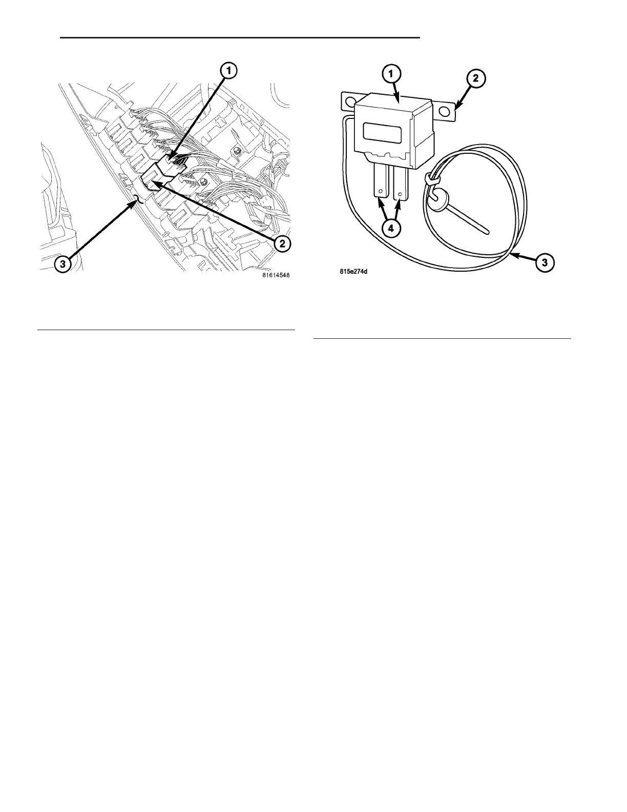
Fig. 14 Rear A/C Blower Motor Switch
1 - WIRE HARNESS CONNECTOR
2 - REAR A/C BLOWER MOTOR SWITCH
3 - ACCESSORY SWITCH PANEL
Fig. 15 Rear Evaporator Temperature Sensor
1 - SWITCH UNIT
2 - MOUNTING TAB (2)
3 - CAPILLARY TUBE
4 - WIRE CONNECTORS
VA CONTROLS - REAR 24 - 37