INSTALLATION
(1) Position the r ear evapora tor temper atur e sen-
sor t o the rear A/C eva por ator housing.
(2) In st all t he two screws th at secure the r ear
evapor ator tem perat ure sen sor t o the rear A/C evap-
orator housing. Tigh ten the screws to 2 N·m (17 in.
lbs.).
(3) In st all the sensor probe int o the rear A/C evap-
orator.
(4) Connect the t wo wire h arness con nector s to t he
rear evaporator tem perat ure sen sor.
(5) In st all th e rea r air filter (Refer to 24 - HEAT-
ING & AIR CONDITIONING/DISTRIBUTION -
REAR/AIR FILTE R - INSTALLATION).
(6) Reconnect t he negat ive batt ery cable.
TEMPERATURE CONTROL
DESCRIPTION
The tem per atu re control for the optional rear A/C
system is a th umbwheel-type control mou nted in the
switch pa nel on th e instrument pa nel (Fig. 17). The
rear A/C tem perat ure cont rol a llows the selection of
four tem perature settings when t he r ear A/C blower
motor is activat ed.
OPERATION
With th e front A/C switch and rea r blower mot or
activat ed, th e rear A/C output tempera tur e can be
selected by rotatin g the thumbwheel control upwards
(increase cooling) or downwards (decr ease cooling).
Depending on t he r ear A/C t empera ture cont rol posi-
tion, a tempera ture command signal is sent to th e
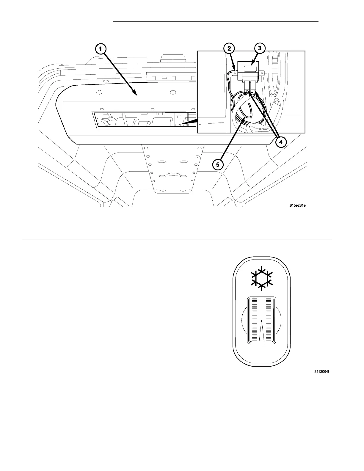
Fig. 16 Rear Evaporator Temperature Sensor
1 - REAR A/C EVAPORATOR HOUSING
2 - SCREWS (2)
3 - REAR EVAPORATOR SENSOR SWITCH UNIT
4 - WIRE HARNESS CONNECTORS
5 - REAR EVAPORATOR SENSOR PROBE
Fig. 17 Rear A/C Temperature Control
24 - 38 CON T R OL S - R EAR VA