rear A/C control module. The t empera ture of the cir-
cula ted inter nal a ir of th e r ear compart ment is mea -
su red by a tempera ture sensor locat ed in the r ear
evapor ator unit. The value of the tem perat ure sensor
is compar ed in th e rear A/C contr ol module with a n
adju st ed value a t the r ear A/C temper atu re cont rol.
The rear A/C tempera ture con trol cannot be
repaired a nd, if faulty or dam aged, it must be
repla ced.
DI AGN OSI S AN D T EST I N G
REAR A / C TEMPERA TURE CONTROL
Before test ing the r ear A/C t empera ture contr ol,
verify th at the front A/C system is opera ting correct ly
by perfor min g the ATC Fu nction Test using t he
DRBII I! sca n tool. Use a volt/ohmmeter to t est th e
control. For circu it descr iptions a nd diagr ams, refer
to the appropriate wirin g infor mation. The wir ing
information inclu des wir ing diagr ams, proper wire
and con nector r epair procedures, details of wire har-
ness r outing a nd r etent ion, connector pin-ou t infor-
mation and location views for the various wir e
harness connectors, splices an d grounds.
WARNING: To avoid personal injury or death, on
vehicles equipped with airbags, disable the supple-
mental restraint system before attempting any
steering wheel, steering column, airbag, seat belt
tensioner, impact sensor, or instrument panel com-
ponent diagnosis or service. Disconnect and isolate
the battery negative (ground) cable, then wait two
minutes for the system capacitor to discharge
before performing further diagnosis or service. This
is the only sure way to disable the supplemental
restraint system. Failure to take the proper precau-
tions could result in accidental airbag deployment.
(1) Disconn ect and isolate the battery nega tive
cable.
(2) Unplug the wir e ha rness con nector from th e
rear A/C tem perature con trol.
(3) Check for con tinuity between ter mina l 9 a nd
term inals 3 a nd 5 of th e A/C temper atu re control. In
all instances, there sh ould be continuity.
NOTE: To check the switch’s internal circuits, con-
nect the positive lead of the ohmmeter to terminal 9
and the negative lead to terminals 3 and 5. To
check the switches integral light emitting diode,
reverse the ohmmeter leads.
(4) Check for r esistance between termina l 3 an d 5
of the A/C t empera tur e control as you m ove th e con-
trol to ea ch tempera ture position . Resista nce should
be presen t and shou ld chan ge for ea ch position .
(5) If OK, test and repair th e rear A/C tem pera-
ture control wire ha rness cir cuits. If not OK, replace
the fa ult y rea r A/C tempera ture contr ol.
REMOVAL
WARNING: To avoid personal injury or death, on
vehicles equipped with airbags, disable the supple-
mental restraint system before attempting any
steering wheel, steering column, airbag, seat belt
tensioner, impact sensor, or instrument panel com-
ponent diagnosis or service. Disconnect and isolate
the battery negative (ground) cable, then wait two
minutes for the system capacitor to discharge
before performing further diagnosis or service. This
is the only sure way to disable the supplemental
restraint system. Failure to take the proper precau-
tions could result in accidental airbag deployment.
NOTE: The rear A/C temperature control is used
only on models with the optional rear A/C unit.
(1) Disconn ect and isolate the negat ive ba tter y
cable.
(2) Remove t he a ccessor y switch pa nel from the
instr umen t panel (Refer to 23 - BODY/INSTRU-
MENT PANEL/ACCESSORY SWITCH BEZEL -
REMOVAL).
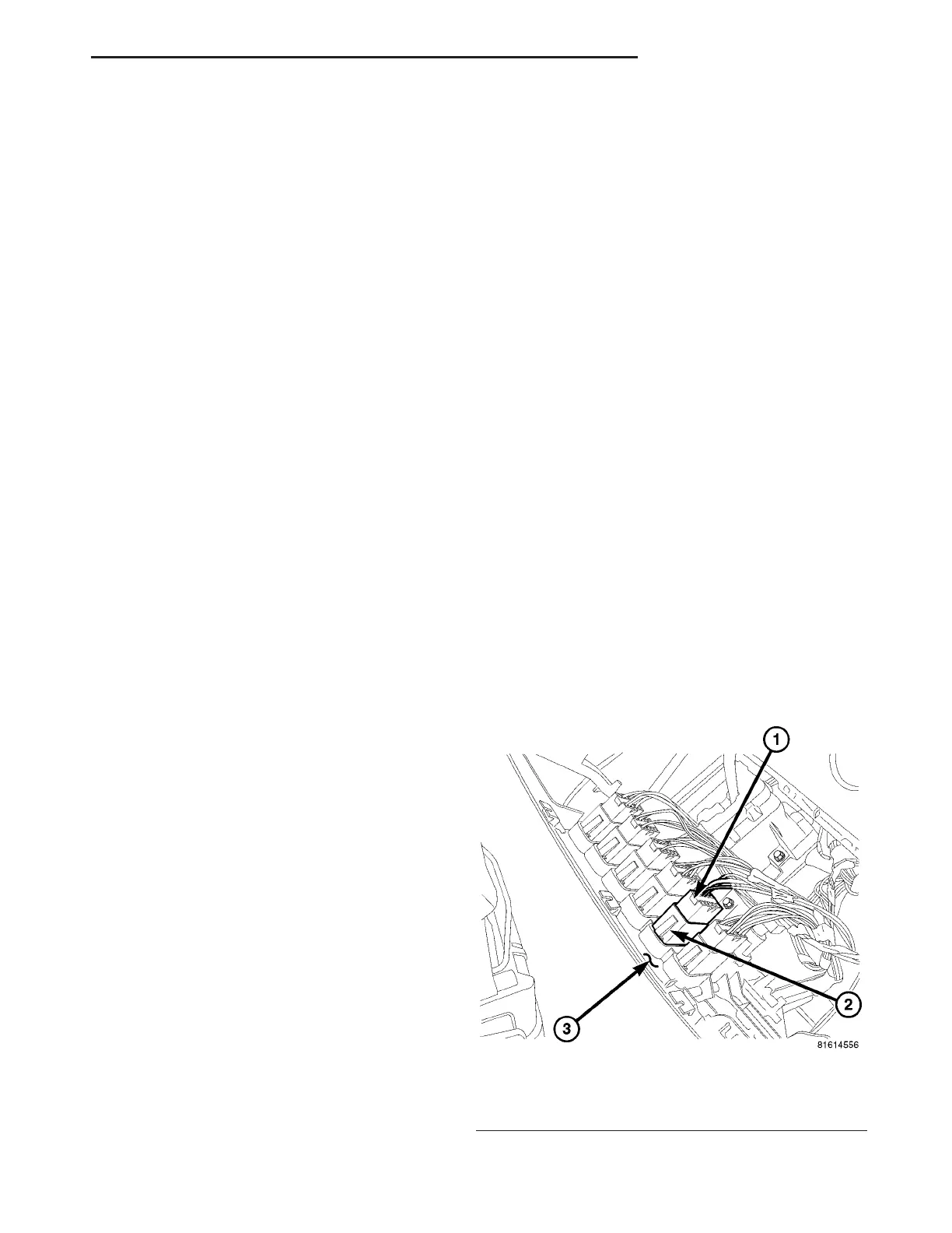
(3) Disconn ect the wire ha rness connector from th e
rear A/C tem perature con trol (Fig. 18).
(4) Disengage the retainin g t abs and rem ove the
rear A/C tempera ture contr ol from t he accessory
switch panel.
Fig. 18 Rear A/C Temperature Control
1 - WIRE HARNESS CONNECTOR
2 - REAR A/C TEMPERATURE CONTROL
3 - ACCESSORY SWITCH PANEL
VA CONTROLS - REAR 24 - 39