INSTALLATION
(1) In st all th e rea r A/C tempera ture contr ol into
the accessor y switch pan el. Ma ke sur e th e ret aining
tabs a re fully engaged.
(2) Connect the wire harness connector to th e rear
A/C temper ature control.
(3) In st all the accessory switch panel (Refer to 23 -
BODY/INSTRUMENT PANE L/ACCESSORY
SWITCH BEZE L - INSTALLATION).
(4) Reconnect t he negat ive batt ery cable.
TEMPERATURE SENSOR
DESCRIPTION
The rear temper ature sensor (Fig. 19) provides an
air outlet tem per atu re signa l t o the rea r A/C contr ol
module thr ough a two-wire h arness lead a nd connec-
tor.
The rear temper atur e sensor is locat ed in the rea r
A/C eva por ator hou sing.
OPERATION
The rea r A/C t empera ture sensor is a variable
resistor that opera tes on a five-volt refer ence signal
sent t o it by the rea r A/C cont rol module. The resis-
tance in t he sensor chan ges as a ir temper ature
changes. Based upon the resistan ce in the sensor, a
specific voltage on the temperature sensor signal cir-
cuit is ret urned t o the rear A/C con trol m odu le,
which is progr ammed to correspond to a specific tem-
pera tu re.
The rea r A/C temper ature sensor can not be
adju st ed or repa ired and, if faulty or dam aged, it
must be r eplaced.
DI AGN OSI S AN D T EST I N G
REAR TEMPERA TURE SENSOR
(1) Disconn ect and isolate the negat ive ba tter y
cable.
(2) Disconn ect the wire ha rness connector from th e
rear t empera ture sensor.
(3) Measur e the r esista nce of the r ear tem perat ure
sensor. At –40° C (–40° F), the sensor resista nce
sh ould be approxima tley 336 kiloh ms. At 55° C (131°
F), the sensor resistan ce is shou ld be approximaytly
25 kiloh ms. Th e rea r sensor r esistance should read
bet ween t h ese t wo va lues.
(4) If OK, test an d repair th e rea r tempera ture
sensor wire harness circuits. Refer to the appropriate
wiring infor mation for rear tempera ture sensor cir-
cuit descript ions and for complete HVAC wir ing dia-
gra ms. If not OK, replace t he faulty tempera tur e
sensor (Refer t o 24 - HE ATING & AIR CONDITION-
ING/CONTROLS - RE AR/TEMPERATURE SENSOR
- REMOVAL).
REMOVAL
(1) Disconn ect and isolate the negat ive ba tter y
cable.
(2) Remove th e air filter from the rea r A/C evapo-
rator hou sing (Refer t o 24 - H EATING & AIR CON-
DITIONING/DISTRIBUTION - REAR/AIR F ILTER -
REMOVAL).
(3) Reach up int o the rear A/C evaporator hou sing
and disconnect the wire ha rness connector from the
rear t empera ture sensor (Fig. 20).
(4) Carefully remove th e rear tempera ture sen sor
from the bracket.
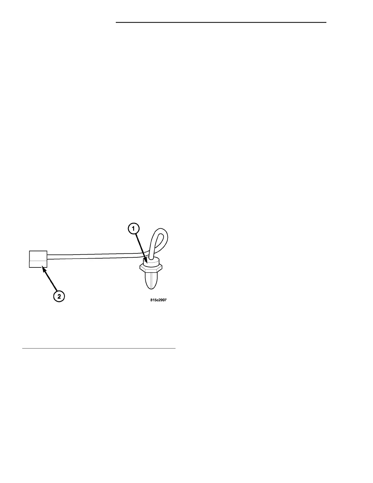
Fig. 19 Rear Temperature Sensor
1 - REAR TEMPERATURE SENSOR
2 - WIRE HARNESS CONNECTOR
24 - 40 CON T R OL S - R EAR VA