INSTALLATION
(1) Carefully install th e r ear temperatur e sen sor
onto th e bracket loca ted in the rea r A/C evaporator
housin g.
(2) Connect the tempera ture sensor wire harness
connect or.
(3) Connect the wire harness connector to th e rear
temper ature sensor.
(4) In st all th e rea r air filter (Refer to 24 - HEAT-
ING & AIR CONDITIONING/DISTRIBUTION -
REAR/AIR FILTE R - INSTALLATION).
(5) Reconnect t he negat ive batt ery cable.
SU PPRESSOR FI LT ER - REAR
BLOWER M OT OR
DESCRIPTION
The two in terfer ence suppression filters (Fig. 21)
for the two rear blower mot ors pr otects t he rea r A/C
control circuits and the vehicles electr ical system
from volt age spikes which may be gen erat ed by t he
two blower motors or t he t hree rear blower motor
rela ys. Th e suppression filters also impede t he prop-
aga tion of RF interfer ence in to the vehicles electrical
system by t he rea r blower motor s to en su re in terfer-
ence-free radio reception.
The rear blower motor suppression filter s a re
locat ed near t he r ear blower mot ors in the rear A/C
evapor ator hou sing.
OPERATION
The rear blower motor suppression filters provide
pr otection against tr ansient interference signa ls or
similar int erference to th e elect ronic rear blower
motor circuits wh ich ca n effect the performan ce of
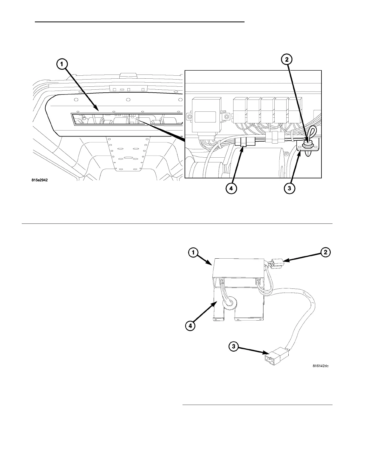
Fig. 20 Rear Temperature Sensor
1 - REAR A/C EVAPORATOR HOUSING
2 - TEMPERATURE SENSOR
3 - BRACKET
4 - WIRE HARNESS CONNECTOR
Fig. 21 Rear Blower Motor Suppression Filter
1 - REAR BLOWER MOTOR SUPPRESSION FILTER (2)
2 - WIRE CONNECTOR (TO BLOWER MOTOR)
3 - WIRE CONNECTOR (TO REAR A/C HARNESS)
4 - MOUNTING BRACKET
VA CONTROLS - REAR 24 - 41