INSTALLATION
(1) Position t he rea r blower m otor su ppression fil-
ter being serviced to th e rear A/C evaporator hou s-
ing.
(2) In st all the scr ew that secur es each r ear blower
motor su ppression fi lter to the rear A/C evapora tor
housin g. Tight en the scr ew(s) to 2 N·m (17 in. lbs.).
(3) Connect th e two su ppression filter wire har-
ness connect ors.
(4) In st all the cover onto the rear A/C evaporator
housin g (Refer to 24 - H EATING & AIR CONDI-
TIONING/DISTRIBUTION - REAR/A/C EVAPORA-
TOR COVE R-REAR - INSTALLATION).
(5) Reconnect t he negat ive batt ery cable.
SU PPRESSOR FI LT ER - REAR
CON DEN SER FAN
DESCRIPTION
The in terfer ence suppression filt er (Fig. 23) for th e
rear A/C condenser fan protects th e rea r A/C cont rol
circuits an d the vehicles electr ical system fr om volt -
age spikes which may be gen erated by the rear con-
denser fa n motor or th e rea r conden ser fan relay. Th e
su ppression filt er also impedes th e pr opa gation of RF
interference into t he vehicles electrical system by the
rear conden ser fan to ensure interference-free radio
reception.
The rea r con denser fan suppression filt er is located
in th e r ear A/C condenser h ousing near t he rea r con -
denser fan.
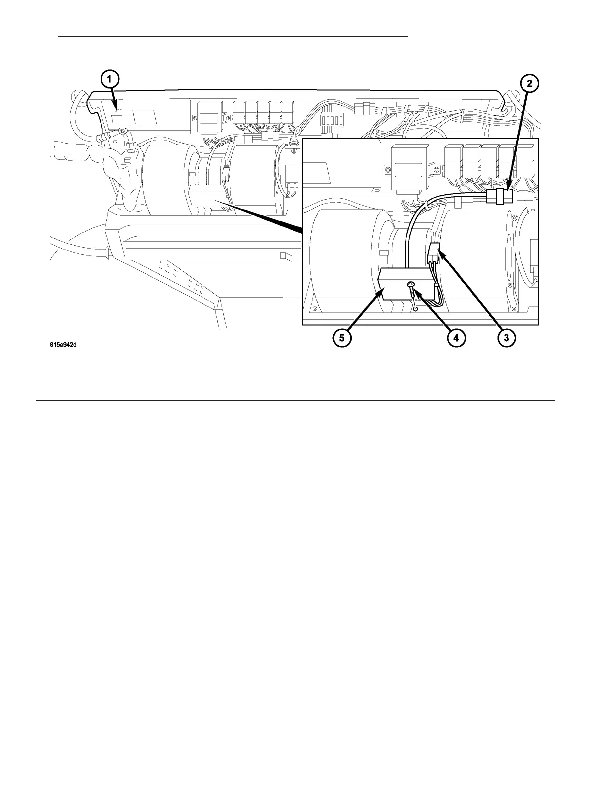
Fig. 22 Rear Blower Motor Suppression Filter – LH shown, RH similar
1 - REAR A/C EVAPORATOR HOUSING
2 - SUPPRESSION FILTER WIRE CONNECTOR
3 - BLOWER MOTOR WIRE CONNECTOR
4 - SCREW
5 - REAR BLOWER MOTOR SUPPRESSION FILTER (2)
VA CONTROLS - REAR 24 - 43