(15) Reconn ect the n egative battery cable.
(16) Eva cuat e th e rear refriger ant system (Refer t o
24 - HEATING & AIR CONDITIONING/P LUMBING
- STANDARD PROCEDURE - REFRIGERANT SYS-
TEM EVACUATE).
(17) Charge th e rear refr iger ant syst em (Refer to
24 - HEATING & AIR CONDITIONING/P LUMBING
- STANDARD PROCEDURE - REFRIGERANT SYS-
TEM CH ARGE).
(18) Install th e rear air filter (Refer t o 24 - HEAT-
ING & AIR CONDITIONING/DISTRIBUTION -
REAR/AIR FILTE R - INSTALLATION).
(19) Install t he cover onto the rear A/C condenser
housin g (Refer to 24 - H EATING & AIR CONDI-
TIONING/DISTRIBUTION - REAR/A/C CON-
DENSER COVE R - INSTALLATION).
A/CEVAPORAT OR COV ER
REMOVAL
(1) Disconn ect and isolate the negat ive ba tter y
cable.
(2) Remove the rea r dom e lamps from the center
and rea r roof duct pan els (Fig. 3).
(3) Remove th e push-pin fasten ers that secur e th e
center and rear roof duct panels to the roof duct and
remove th e panels.
(4) Disconn ect t he dome light wire ha rness connec-
tor and remove t he dome light wire har ness from t he
roof duct .
(5) Remove the six screws that secure t he rea r A/C
evapor ator cover to the fron t of the r ear A/C evapo-
rator housing.
(6) Remove t he thr ee pu sh -pin fasteners t hat
secure the rear A/C evapor ator cover to t he rea r of
the evapor ator hou sing and r emove the cover.
INSTALLATION
(1) Position the rea r A/C evapor ator cover to the
rear A/C eva por ator housing.
(2) In st all the three pu sh -pin fast eners that secu re
the rear A/C evapora tor cover to the rear of the evap-
orator housing.
(3) In st all t he six screws th at secu re the rear A/C
evapor ator cover to the front of the evapora tor hous-
ing. Tighten t he screws to 2.2 N·m (21 in. lbs.).
(4) In st all th e dome light wire ha rness t o th e roof
du ct and reconnect t he ha rness.
(5) Position the cent er an d r ear roof duct pa nels to
the r oof duct an d insta ll t he push-pin fasten ers.
(6) In st all the rea r dome lam ps into the cent er and
rear r oof duct panels.
(7) Reconnect t he negat ive batt ery cable.
A/CEVAPORAT OR H OU SI N G
REMOVAL
WARNING: Refer to the applicable warnings and
cautions for this system before performing the fol-
lowing operation (Refer to 24 - HEATING & AIR
CONDITIONING/PLUMBING - WARNINGS) and (Refer
to 24 - HEATING & AIR CONDITIONING/PLUMBING -
CAUTIONS). Failure to follow the warnings and cau-
tions could result in possible personal injury or
death.
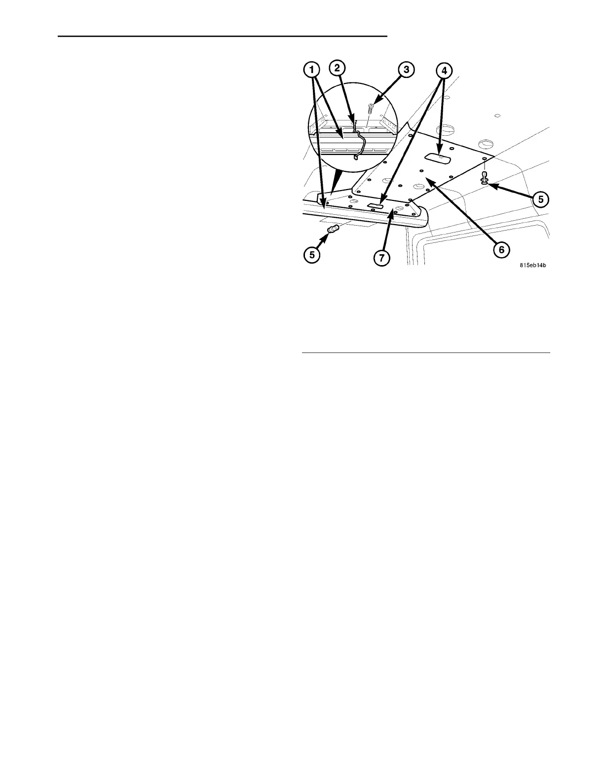
Fig. 3 Rear A/C Evaporator Cover
1 - REAR A/C EVAPORATOR COVER
2 - DOME LAMP WIRE HARNESS
3 - SCREW (6)
4 - REAR DOME LAMPS
5 - PUSH-PIN FASTENER (22)
6 - CENTER ROOF DUCT PANEL
7 - REAR ROOF DUCT PANEL
VA DISTRIBUTION - REAR 24 - 55