ther e a re no objects placed in fron t of the r adiator
grille open ings in t he front of th e vehicle or foreign
mater ial on the condenser fins that might obstr uct
pr oper air flow. Also, any fa ctory-inst alled air seals or
sh rouds must be proper ly reinsta lled following ra dia-
tor or condenser ser vice.
The con denser can not be r epair ed and, if fa ulty or
da maged, it must be replaced.
REMOVAL
WARNING: Refer to the applicable warnings and
cautions for this system before performing the fol-
lowing operation (Refer to 24 - HEATING & AIR
CONDITIONING/PLUMBING - WARNINGS) and (Refer
to 24 - HEATING & AIR CONDITIONING/PLUMBING -
CAUTIONS). Failure to follow the warnings and cau-
tions could result in possible personal injury or
death.
(1) Disconn ect and isolate the negat ive ba tter y
cable.
(2) Recover th e refriger ant from th e refriger ant
system (Refer t o 24 - HEATING & AIR CONDITION-
ING/PLUMBING - STANDARD PROCE DURE -
REFRIGERANT SYSTEM RECOVE RY).
(3) Remove the front fascia.
(4) Remove the gr ille (Refer to 23 - BODY/EXTE-
RIOR/GRILLE - REMOVAL).
(5) Remove the headlamps fr om their mounts.
(6) Remove t he radiator crossmember (Refer to 23
- BODY/EXTERIOR/RADIATOR CROSSME MBER -
REMOVAL).
(7) Disconn ect the A/C discharge an d liquid lin es
from the A/C conden ser a nd remove a nd disca rd th e
O-rin g seals (Fig. 6).
(8) In st all plug in, or ta pe over t he opened liquid
lin e fitt ing and the conden ser ports.
(9) Disconn ect the wire ha rness connector from th e
auxiliar y fan.
(10) Remove t he a uxilia ry fan an d upper br acket
assembly.
(11) Remove the auxiliar y fa n lower bra cket
reta iner s a nd bra cket .
(12) Remove th e four conden ser r etaining scr ews.
(13) Carefu lly remove th e conden ser from the vehi-
cle.
INSTALLATION
NOTE: If the A/C condenser is being replaced, add
30 milliliters (1 fluid ounce) of refrigerant oil to the
refrigerant system. Use only refrigerant oil of the
type recommended for the A/C compressor in the
vehicle.
(1) Carefully position the A/C condenser into th e
engine com pa rtmen t.
(2) In st all th e four screws that secure the A/C con-
denser. Tighten t he screws to 2 N·m (17 in. lbs.).
(3) In st all the lower auxiliary fan br acket and
reta ining n uts. Tighten the nut s to 5 N·m (45 in .
lbs.).
(4) In st all the a uxiliary fa n and upper bracket
assembly. Tighten the screws to 5 N·m (45 in. lbs.).
(5) Connect th e wire harness connector t o the aux-
iliary fan .
(6) Remove the tape or plug from th e condenser
por ts and the opened r efrigera nt line fittings.
(7) Lubricate a new rubber O-rin g seal with clean
refriger ant oil and insta ll it on th e refrigera nt line
fittings.
(8) Connect t he A/C disch arge and liquid lines to
the A/C condenser.
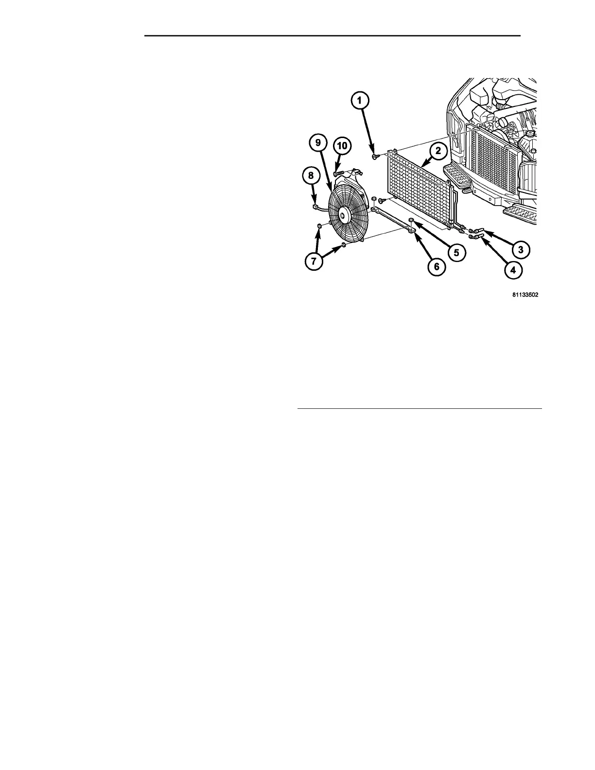
Fig. 6 A/C Condenser
1 - SCREW (4)
2 - CONDENSER
3 - LIQUID REFRIGERANT LINE
4 - COMPRESSOR DISCHARGE LINE
5 - NUT (2)
6 - LOWER AUXILIARY FAN BRACKET
7 - NUT (2)
8 - WIRE HARNESS CONNECTOR
9 - AUXILIARY COOLING FAN
10 - SCREW (2)
24 - 70 PLUMBING VA