(9) In st all the nut s th at secu re the A/C discharge
and liquid lines to the A/C condenser. Tight en the
nuts to 33 N·m (24 ft. lbs.).
(10) Install the r adiator crossmember (Refer to 23
- BODY/EXTERIOR/RADIATOR CROSSME MBER -
INSTALLATION).
(11) In st all the headlamps into their mounts.
(12) Install t he gr ille (Refer to 23 - BODY/EXTE-
RIOR/GRILLE - INSTALLATION).
(13) Install the front fascia.
(14) Reconn ect the n egative battery cable.
(15) Eva cuat e the refr iger ant system (Refer to 24 -
HEATING & AIR CONDITIONING/PLUMBING -
STANDARD PROCEDURE - REFRIGE RANT SYS-
TEM EVACUATE).
(16) Recha rge the refriger ant system (Refer to 24 -
HEATING & AIR CONDITIONING/PLUMBING -
STANDARD PROCEDURE - REFRIGE RANT SYS-
TEM CH ARGE).
A/CDISCHARGELINE
REMOVAL
WARNING: Refer to the applicable warnings and
cautions for this system before performing the fol-
lowing operation (Refer to 24 - HEATING & AIR
CONDITIONING/PLUMBING - WARNINGS) and (Refer
to 24 - HEATING & AIR CONDITIONING/PLUMBING -
CAUTIONS). Failure to follow the warnings and cau-
tions could result in possible personal injury or
death.
(1) Disconn ect and isolate the negat ive ba tter y
cable.
(2) Recover th e refriger ant from th e refriger ant
system (Refer t o 24 - HEATING & AIR CONDITION-
ING/PLUMBING - STANDARD PROCE DURE -
REFRIGERANT RECOVERY).
(3) Remove the gr ille (Refer to 23 - BODY/EXTE-
RIOR/GRILLE - REMOVAL).
(4) Remove t he n ut tha t secures th e disch arge line
fitting to t he condenser on t he left side of t he con-
denser.
(5) Disconn ect the discharge line fit tin g from t he
condenser inlet por t.
(6) Remove the sea l from the discha rge line fitting
and disca rd.
(7) In st all plug in, or ta pe over the opened dis-
charge line fitting and the conden ser inlet port.
(8) Remove the bolt tha t secu res the discharge line
fitting to the top of t he compr essor (Fig. 7).
(9) Disconn ect the discharge line fit tin g from t he
compressor discha rge por t.
(10) Remove the seal from the discha rge line fit-
ting and disca rd.
(11) In st all plug in, or tape over the open ed dis-
charge line fitting and th e compressor discharge por t.
(12) Disconn ect th e dischar ge line from the retain-
ing clip and remove t he dischar ge line from the vehi-
cle.
INSTALLATION
Any kinks or sharp bends in the refr igeran t plumb-
ing will r educe the capacity of t he entire air condi-
tioning system . Kinks and shar p ben ds reduce the
flow of refriger ant in the syst em. A good rule for th e
flexible hose refrigerant lines is to keep th e radius of
all bends at least ten times the diameter of t he hose.
In addition, the flexible h ose refr iger ant lines should
be routed so th ey are at lea st 80 millimet ers (3
inches) from the exhaust manifold.
(1) Position the discharge line in to th e en gin e com-
part ment .
(2) Remove the tape or plugs from th e compressor
dischar ge port a nd the discharge line fitting.
(3) Lubricate a new rubber O-rin g seal with clean
refriger ant oil an d in st all it on the discharge lin e fit-
ting.
(4) Connect t he discha rge line fitting to the com-
pr essor discharge port on th e top of the compressor.
(5) In st all the bolt that secur es t he discha rge line
fitting to th e com pr essor. Tighten th e bolt to 23 N·m
(17 ft. lbs.).
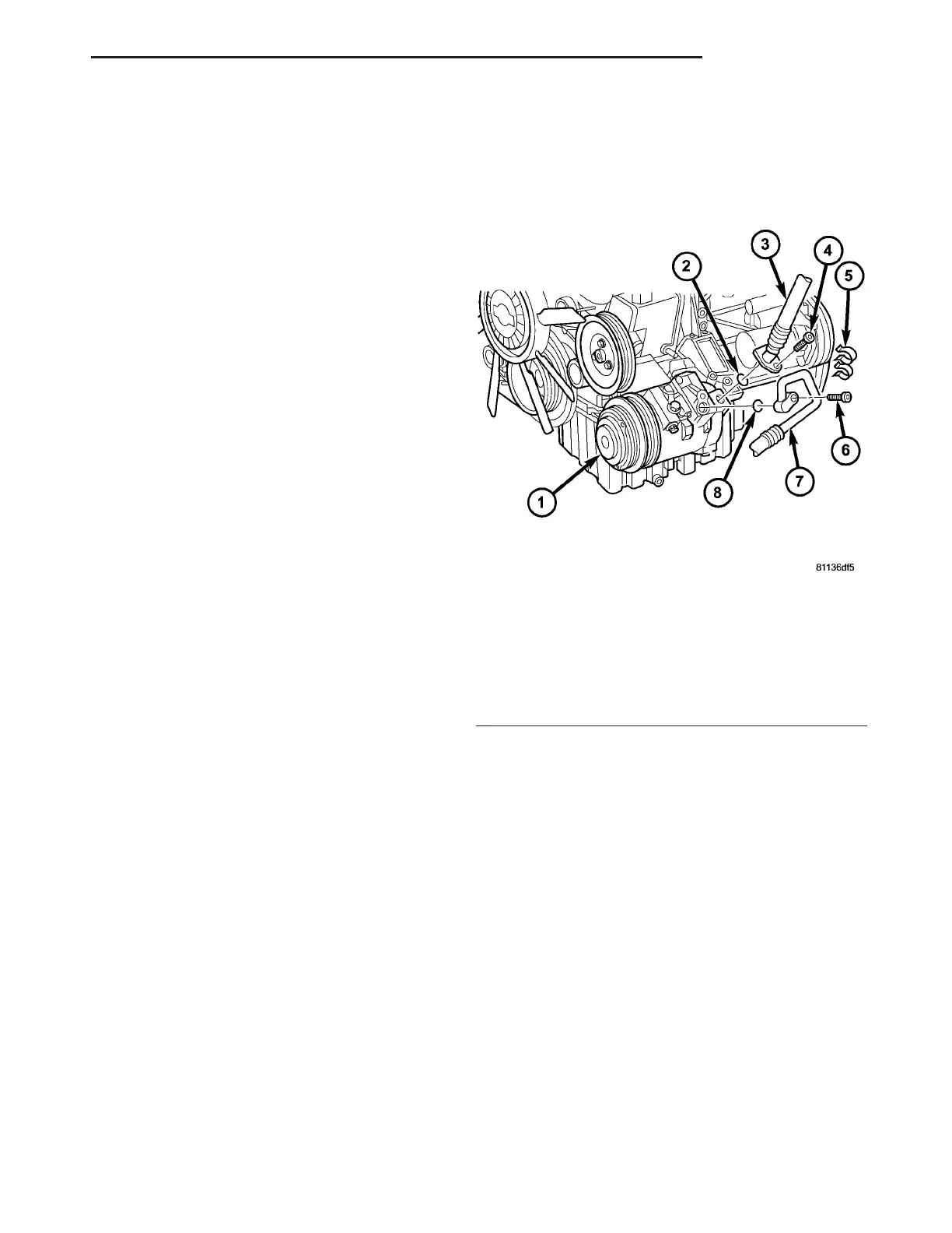
Fig. 7 A/C Compressor - Refrigerant Lines
1 - A/C COMPRESSOR
2 - O-RING SEAL
3 - A/C SUCTION LINE
4 - BOLT
5 - RETAINING CLIP
6 - BOLT
7 - A/C DISCHARGE LINE
8 - O-RING SEAL
VA PLUMBING 24 - 71