WARNING: Refer to the applicable warnings and
cautions for this system before performing the fol-
lowing operation (Refer to 24 - HEATING & AIR
CONDITIONING/PLUMBING - WARNINGS) and (Refer
to 24 - HEATING & AIR CONDITIONING/PLUMBING -
CAUTIONS). Failure to follow the warnings and cau-
tions could result in possible personal injury or
death.
(1) Remove the HVAC h ousing (Refer to 24 -
HEATING & AIR CONDITIONING/DISTRIBUTION/
HVAC HOUSING - RE MOVAL).
(2) Disassem ble the HVAC housing to access the
A/C evaporator (Refer t o 24 - H EATING & AIR CON-
DITIONING/DISTRIBUTION/HVAC HOUSING -
DISASSEMBLY).
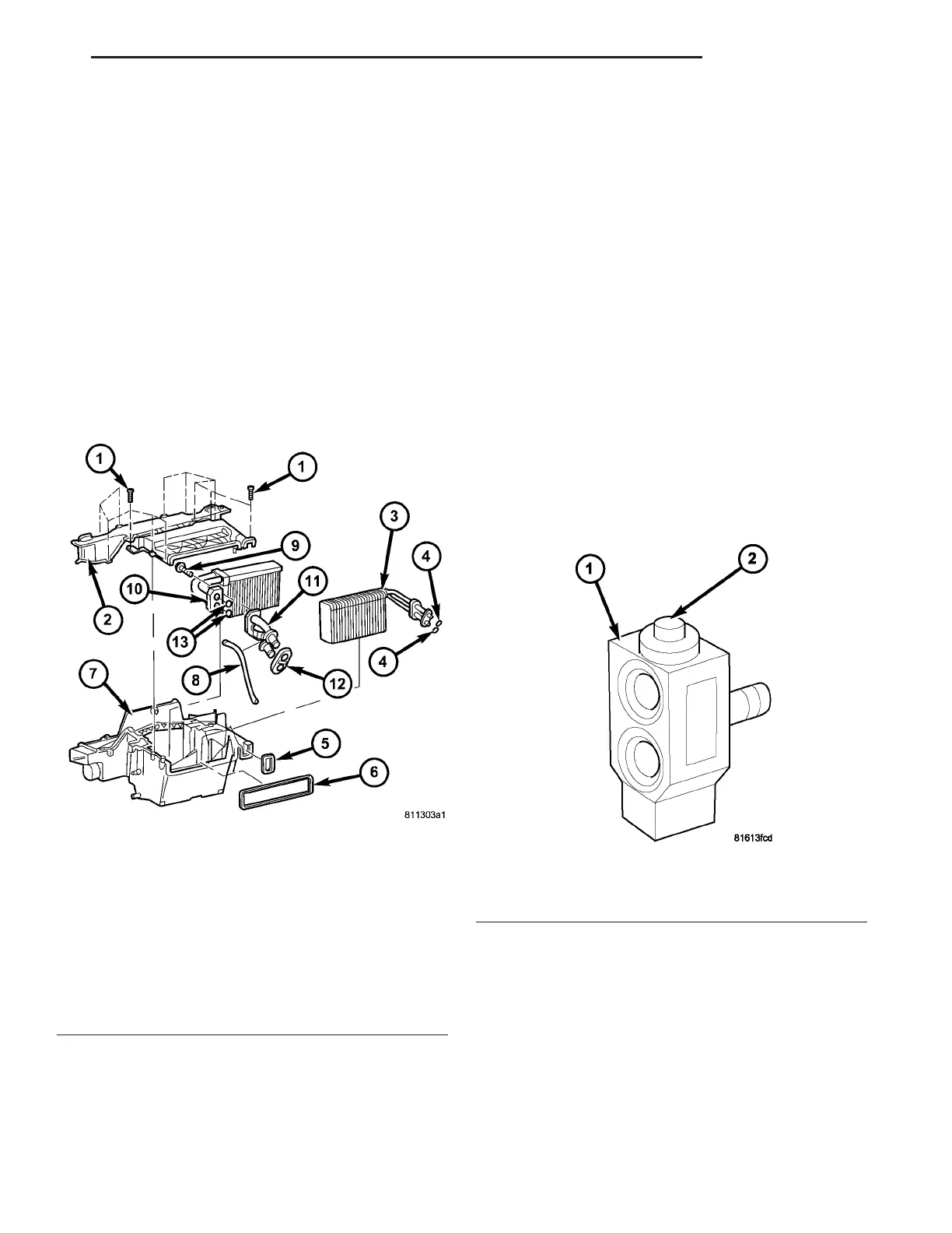
(3) Lift th e A/C evaporator out of t he lower h alf of
the H VAC housing (Fig. 9).
INSTALLATION
NOTE: If the A/C evaporator is being replaced, add
60 milliliters (2 fluid ounces) of refrigerant oil to the
refrigerant system. Use only refrigerant oil of the
type recommended for the A/C compressor in the
vehicle.
(1) In st all the A/C evapora tor in to t he lower half of
the H VAC housing.
(2) Assem ble th e HVAC housing (Refer to 24 -
HEATING & AIR CONDITIONING/DISTRIBUTION/
HVAC HOUSING - ASSEMBLY).
(3) In st all t he HVAC housing (Refer to 24 - H EAT-
ING & AIR CONDITIONING/DISTRIBUTION/HVAC
HOUSING - INSTALLATION).
A/CEXPANSIONVALVE
DESCRIPTION
The A/C expansion valve controls the a mount of
refriger ant en tering the A/C eva por ator an d is of a
ther mostat ic expan sion valve (TXV) design (Fig. 10).
The A/C expan sion valve consists of an a luminum
H-va lve t ype body with an int egra l th erma l sensor.
The A/C expa nsion valve is located at the dash
pa nel between the A/C refrigera nt lines and the A/C
evapor ator.
OPERATION
High-pressure, high tempera ture liquid r efrigera nt
from the liqu id line passes through the expansion
valve orifice, con vert ing it in to a low-pressur e, low-
temper ature mixt ure of liqu id an d gas before it
enters the A/C evaporator. A t herm al sensor in th e
A/C expansion valve monitors the tempera ture of the
refriger ant leaving t he A/C evaporator and adjusts
the orifice size at the evapora tor inlet to allow the
pr oper amount of refriger ant i n to th e A/C evaporator
Fig. 9 HVAC Housing
1 - SCREW (12)
2 - UPPER HOUSING
3 - A/C EVAPORATOR
4 - EVAPORATOR O-RING SEAL (2)
5 - EVAPORATOR GASKET
6 - VENTILATION HOUSING GASKET
7 - LOWER HOUSING
8 - WIRING HARNESS
9 - BOLT (3)
10 - HEATER CORE
11 - HEATER CORE TUBE ASSEMBLY
12 - HEATER CORE TUBE GASKET
13 - HEATER CORE TUBE O-RING SEAL (2)
Fig. 10 Front A/C Expansion Valve
1 - A/C EXPANSION VALVE
2 - THERMAL SENSOR
VA PLUMBING 24 - 73