in order to meet vehicle cooling requ irem ents. Con-
trollin g the refrigerant flow t hrough th e A/C eva po-
rator en su res tha t n one of the refr igeran t leaving the
evapor ator is st ill in a liquid sta te, wh ich could cause
da mage to the A/C com pr essor.
The A/C expa nsion valve is factory calibr ated and
cannot be adjusted or repa ired a nd, if faulty or dam-
aged, it must be repla ced.
DI AGN OSI S AN D T EST I N G
A / C EXPANSION VALVE
The A/C expan sion va lve is located on th e engin e
side of the dash panel nea r the sh ock tower.
The A/C expansion valve ca n fail in t hree different
position s (open, closed or r est rict ed).
In an Open Position : this will resu lt in a n oisy A/C
compressor or no cooling. The cause can be br oken
spring, br oken ball or excessive m oisture in th e A/C
system. If th e spring or ball ar e fou nd to be defective,
repla ce the A/C expansion valve. If excessive mois-
ture is found in the A/C system, recycle th e refriger-
ant.
In a Closed Position : Th ere will be low suction
pr essu re a nd no cooling. This ma y be ca used by a
failed power dome or excessive m oistur e in the A/C
system. If t he power dome on th e A/C expansion
valve is fou nd to be defect ive r eplace t he A/C expa n-
sion va lve. If excessive m oistur e is found recycle the
refriger ant.
A Restricted Orifice: Th ere will be low suct ion
pr essu re and no cooling. This m ay be caused by
debris in the r efrigera nt system. If debr is is believed
to be t he cau se, recycle t he refrigerant and replace
the A/C expansion valve a nd the receiver-drier.
REMOVAL
WARNING: Refer to the applicable warnings and
cautions for this system before performing the fol-
lowing operation (Refer to 24 - HEATING & AIR
CONDITIONING/PLUMBING - WARNINGS) and (Refer
to 24 - HEATING & AIR CONDITIONING/PLUMBING -
CAUTIONS). Failure to follow the warnings and cau-
tions could result in possible personal injury or
death.
(1) Recover the refrigera nt from t he A/C system
(Refer to 24 - HE ATING & AIR CONDITIONING/
PLUMBING - STANDARD PROCEDURE - REFRIG-
ERANT SYSTEM RECOVE RY).
(2) Disconn ect and isolate the negat ive ba tter y
cable.
(3) Remove the nu t th at secu res the suct ion and
liquid line fittings to the st ud on the A/C expansion
valve (F ig. 11).
(4) Disconn ect t he suction and liquid lin es fr om
the expan sion valve.
(5) Remove the sea ls from th e su ction a nd liquid
lin e fitt ing and disca rd.
(6) In st all plugs in, or tape over the open ed liqu id
and su ction line fitt ings an d both expa nsion valve
por ts.
(7) Remove t he t wo bolts that secure th e expan-
sion valve t o the evaporator tube tappin g pla te.
(8) Remove the expan sion valve fr om the evapor a-
tor tube ta pping plate.
(9) Remove the seals from th e evapora tor inlet and
outlet tube fittings and disca rd.
(10) Install plugs in, or tape over t he opened evap-
orator in let and outlet t ube fit tings a nd both expan-
sion valve ports.
INSTALLATION
(1) Remove the tape or plugs from th e tappin g
plate evapora tor inlet and outlet tube fittings and
both ports on the back of the A/C expansion va lve.
(2) Lubricate new rubber O-r ing seals wit h clea n
refriger ant oil and install them on the ta pping plate
evapor ator inlet a nd outlet tu be fittings.
(3) Position the A/C expan sion valve ont o t he tap-
ping plat e eva porator in let an d ou tlet t ube fittings.
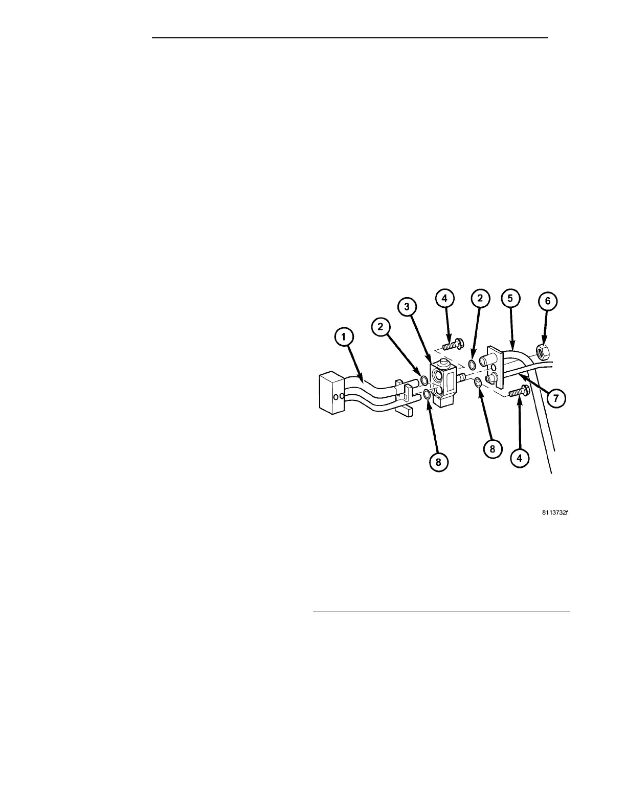
Fig. 11 A/C Expansion Valve
1 - EVAPORATOR TUBE TAPPING PLATE
2 - O-RING SEAL (2)
3 - A/C EXPANSION VALVE
4 - BOLT (2)
5 - A/C SUCTION LINE
6 - NUT
7 - A/C LIQUID LINE
8 - O-RING SEAL (2)
24 - 74 PLUMBING VA