(4) In st all the two bolts tha t secu re the A/C expan -
sion valve to the evaporator tube tapping pla te.
Tighten t he bolts to 5 N·m (45 in. lbs.).
(5) Remove the tape or plugs from the liquid and
su ction line fitt ings and bot h expansion valve por ts.
(6) Lubricate new rubber O-r ing seals wit h clea n
refriger ant oil an d insta ll them on t he liquid and su c-
tion line fitt ings.
(7) Connect the liqu id line fitting to the A/C expa n-
sion valve.
(8) Connect the suct ion line fitting to t he A/C
expan sion valve.
(9) In st all the nut that secu res t he su ction line
and liquid lin e fitt ings to th e st ud on the A/C expan-
sion valve. Tigh ten the nut to 10 N·m (89 in . lbs.).
(10) Reconn ect the n egative battery cable.
(11) Eva cuate th e r efrigera nt system (Refer t o 24 -
HEATING & AIR CONDITIONING/PLUMBING -
STANDARD PROCEDURE - REFRIGE RANT SYS-
TEM EVACUATE).
(12) Charge th e refrigerant system (Refer to 24 -
HEATING & AIR CONDITIONING/PLUMBING -
STANDARD PROCEDURE - REFRIGE RANT SYS-
TEM CH ARGE).
ELECT RI C COOLAN T PU M P
DESCRIPTION
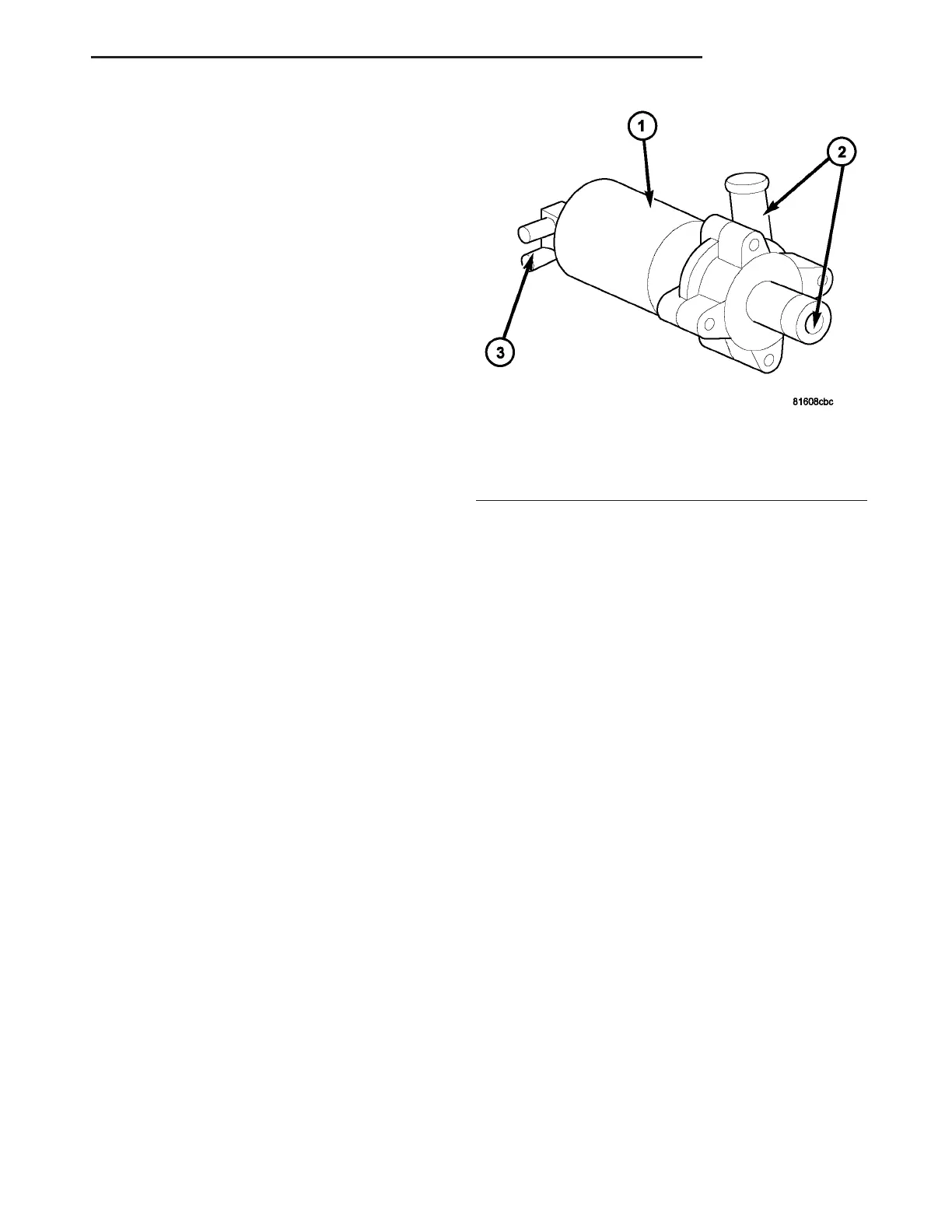
The electric coolant pump ensures the uniform flow
of coola nt through t he hea ter core without bubbles,
even at low speeds (F ig. 12). The electric coolant
pu mp is located in the left side of the engine com-
pa rtmen t near th e ba tter y and is controlled by the
A/C-heater contr ol.
The electric coolan t pump housing con tains t wo
coolan t hose connection s and a n elect ric mot or which
dr ives th e vane-t ype pump using a magnet ic
clutch.
OPERATION
The electr ic coolant pu mp is con trolled by the ATC
A/C-heater cont rol an d is only operationa l when the
ign ition switch is on under the followin g condition s:
(1) Vehicle speed below 27 Km/h (17 mph).
(2) Coolan t tem per atu re above 65° C (150° F) but
less than 110° C (230 ° F ).
(3) Any blower motor speed setting.
(4) Temperatur e heat setting above the halfwa y
setting (60% heat).
(5) The pum p will tur n off at speeds above 48
Km/h (30 m ph ).
(6) The pump will tu rn off if the coolan t tem pera-
ture rises a bove 110° C (230 ° F).
REMOVAL
(1) Disconn ect and isolate the negat ive ba tter y
cable.
(2) Partially drain the engine coolin g system
(Refer to 7 - COOLING/ENGINE/COOLANT - STAN-
DARD PROCE DURE - DRAINING COOLANT SYS-
TEM).
(3) Disconn ect the wire ha rness connector from th e
electric coolant pump (Fig. 13).
(4) Loosen both hose clam ps from th e elect ric cool-
ant pump.
(5) Usin g a twisting motion gen tly rem ove both
heat er hoses from the electric coola nt pump.
(6) Remove the two elect ric coolant pump bra cket
reta ining nuts from the body studs.
(7) Remove the electr ic coola nt pu mp from the
vehicle.
Fig. 12 Electric Coolant Pump
1 - ELECTRIC COOLANT PUMP
2 - COOLANT HOSE CONNECTIONS
3 - WIRE CONNECTOR
VA PLUMBING 24 - 75