INSTALLATION
(1) In st all the electric coola nt pump and m ounting
bracket ont o the body studs.
(2) In st all the two br acket reta ining n uts. Tight en
the n uts to 5 N·m (45 in. lbs.).
(3) Usin g a twistin g motion gent ly inst all both
hoses onto the electric coolant pump.
(4) Tighten bot h hose cla mps securely.
(5) Connect the wire har ness connector to th e elec-
tric coola nt pump.
(6) Reconnect t he negat ive batt ery cable.
(7) Fill the engine cooling syst em (Refer to 7 -
COOLING/ENGINE/COOLANT - STANDARD PRO-
CEDURE - COOLING SYSTEM FILL).
HEATER CORE
DESCRIPTION
The heater cor e is mou nted int o the HVAC hous-
ing, located behind t he instrumen t panel (Fig. 14).
The hea ter core is a hea t exchan ger made of rows of
tubes and fins. The hea ter core tubes are at tached to
the h eater core by usin g O-ring seals a nd bolt s.
The hea ter cor e is serviced by removing and disa s-
sembling the HVAC housing.
OPERATION
Engine coolan t is circulat ed throu gh the heat er
hoses t o the heater core wh enever t he heater wa ter
valve is cycled open by the ATC A/C-heater cont rol.
As the coola nt flows through the hea ter core, hea t
removed from t he engin e is tra nsferred t o the hea ter
core fins a nd tu bes. Air directed throu gh t he heat er
core picks up the h eat from t he hea ter cor e fins. Th e
heat er wa ter valve contr ols the heater output air
temper ature by contr olling the amount of hea ted
engine coola nt flowin g th rough t he heat er cor e. The
blower motor speed cont rols t he volum e of air flowing
through th e HVAC housing.
The heater core cannot be repa ired and, if fau lty or
da maged, it must be replaced.
REMOVAL
WARNING: To avoid personal injury or death, on
vehicles equipped with airbags, disable the supple-
mental restraint system before attempting any
steering wheel, steering column, airbag, seat belt
tensioner, impact sensor, or instrument panel com-
ponent diagnosis or service. Disconnect and isolate
the battery negative (ground) cable, then wait two
minutes for the system capacitor to discharge
before performing further diagnosis or service. This
is the only sure way to disable the supplemental
restraint system. Failure to take the proper precau-
tions could result in accidental airbag deployment.
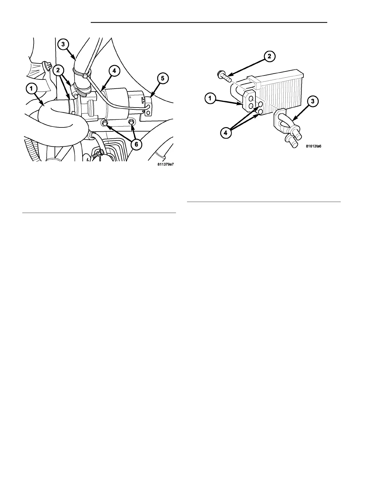
Fig. 13 Electric Coolant Pump
1 - HEATER HOSE
2 - HOSE CLAMP (2)
3 - HEATER HOSE
4 - ELECTRIC COOLANT PUMP
5 - WIRE HARNESS CONNECTOR
6 - NUT (2)
Fig. 14 Front Heater Core
1 - HEATER CORE
2 - BOLT (3)
3 - HEATER CORE TUBES
4 - O-RING SEALS
24 - 76 PLUMBING VA