WARNING: Refer to the applicable warnings and
cautions for this system before performing the fol-
lowing operation (Refer to 24 - HEATING & AIR
CONDITIONING/PLUMBING - WARNINGS) and (Refer
to 24 - HEATING & AIR CONDITIONING/PLUMBING -
CAUTIONS). Failure to follow the warnings and cau-
tions could result in possible personal injury or
death.
(1) Remove the hea ter housing (Refer to 24 -
HEATING & AIR CONDITIONING/DISTRIBUTION/
HVAC HOUSING - RE MOVAL).
(2) Disassem ble the HVAC housing to access the
heat er core (Refer to 24 - H EATING & AIR CONDI-
TIONING/DISTRIBUTION/HVAC HOUSING - DIS-
ASSEMBLY).
(3) Lift the heat er core out of the lower half of the
HVACr h ousing (Fig. 15).
(4) If necessary, remove the thr ee hea ter cor e tube
reta ining bolts a nd th e heater core tube assembly
from the heater core.
(5) Remove the heater core tube seals and discard
as required.
INSTALLATION
(1) If the heater core tube assem bly wa s rem oved
from th e hea ter cor e, l u bricate two n ew rubber
O-rin g sea ls with clean en gin e coola nt and install
them on to th e heater core fitting.
(2) If required, con nect th e hea ter core tube
assembly to the hea ter core an d insta ll th e three
reta ining bolts. Tighten th e bolts to 5 N·m (45 in.
lbs.).
(3) In st all the h eater cor e into the bottom ha lf of
the H VAC housing.
(4) Assem ble th e HVAC housing (Refer to 24 -
HEATING & AIR CONDITIONING/DISTRIBUTION/
HVAC HOUSING - ASSEMBLY).
NOTE: If the heater core is being replaced, flush the
cooling system (Refer to 7 - COOLING - STANDARD
PROCEDURE - COOLING SYSTEM CLEANING/RE-
VERSE FLUSHING).
(5) In st all t he HVAC housing (Refer to 24 - H EAT-
ING & AIR CONDITIONING/DISTRIBUTION/HVAC
HOUSING - INSTALLATION).
LI QU I D LI N E
REMOVAL
WARNING: Refer to the applicable warnings and
cautions for this system before performing the fol-
lowing operation (Refer to 24 - HEATING & AIR
CONDITIONING/PLUMBING - WARNINGS) and (Refer
to 24 - HEATING & AIR CONDITIONING/PLUMBING -
CAUTIONS). Failure to follow the warnings and cau-
tions could result in possible personal injury or
death.
NOTE: The A/C liquid line is serviced in two sec-
tions. The front section connects between the A/C
condenser and the receiver/drier and includes the
high side service port and the A/C pressure sensor
on the fitting for the receiver/drier. The rear section
connects between the receiver/drier and the A/C
expansion valve.
FRONT SECTION
(1) Recover th e refriger ant from th e refriger ant
system (Refer t o 24 - HEATING & AIR CONDITION-
ING/PLUMBING - STANDARD PROCE DURE -
REFRIGERANT SYSTEM RECOVE RY).
(2) Disconn ect and isolate they negat ive ba tter
cable.
(3) Remove the gr ille (Refer to 23 - BODY/EXTE-
RIOR/GRILLE - REMOVAL).
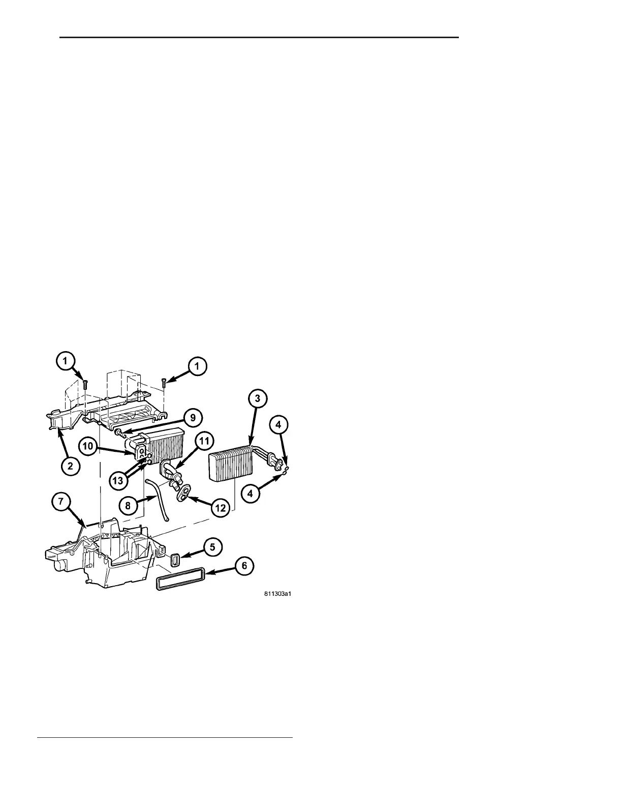
Fig. 15 HVAC Housing
1 - SCREW (12)
2 - UPPER HOUSING
3 - A/C EVAPORATOR
4 - EVAPORATOR O-RING SEAL (2)
5 - EVAPORATOR GASKET
6 - VENTILATION HOUSING GASKET
7 - LOWER HOUSING
8 - WIRING HARNESS
9 - BOLT (3)
10 - HEATER CORE
11 - HEATER CORE TUBE ASSEMBLY
12 - HEATER CORE TUBE GASKET
13 - HEATER CORE TUBE O-RING SEAL (2)
VA PLUMBING 24 - 77