(4) Remove the n ut that secu res th e A/C liqu id line
to th e A/C conden ser.
(5) Disconn ect the A/C liquid lin e to t he A/C con-
denser and r emove and disca rd the O-rin g seal.
(6) In st all plug in, or ta pe over t he opened liquid
lin e fitt ing and the conden ser ou tlet port.
(7) Remove the rout ing clip r etaining n ut and dis-
enga ge th e routin g clip ret ain er on top of th e left
frame rail from the front section of the liqu id line.
(8) Remove the A/C pressu re sensor from th e front
liquid line fitt ing (Refer to 24 - HEATING & AIR
CONDITIONING/CONTROLS/A/C PRESSURE
TRANSDUCER - REMOVAL).
(9) Remove the bolt tha t secures the fron t section
of t he liquid line to the t op of the r eceiver/drier (F ig.
16).
(10) Disconn ect t he fron t section of t he liquid line
from th e receiver /dr ier a nd remove an d disca rd the
O-rin g seal.
(11) In st all plug in , or ta pe over the opened liquid
lin e fitt ing and the receiver/drier inlet port.
(12) Remove the fron t sect ion of t he A/C liquid line
from the engine compartment.
REAR SECTION
(1) Recover th e refriger ant from th e refriger ant
system (Refer t o 24 - HEATING & AIR CONDITION-
ING/PLUMBING/REFRIGERANT - STANDARD
PROCE DURE - REFRIGERANT SYSTEM RECOV-
ERY).
(2) Disconn ect and isolate the negat ive ba tter y
cable.
(3) Remove the gr ille (Refer to 23 - BODY/EXTE-
RIOR/GRILLE - REMOVAL).
(4) Remove the nut that secur es the A/C suction
and liquid lines to the stud on the A/C expansion
valve (F ig. 17).
(5) Disconn ect the A/C suct ion and liqu id lin es
from the A/C expan sion valve and remove and dis-
card the O-ring seals.
(6) Disengage th e routing clip ret ain er from t he
rear sect ion of th e A/C liquid lin e.
(7) Remove the bolt that secu res t he rear section
of t he liquid line to the t op of the r eceiver/drier (F ig.
16).
(8) Disconn ect t he rea r sect ion of the liqu id line
from the receiver /dr ier.
(9) Remove th e seal from the liquid lin e fit tin g
outlet port and disca rd.
(10) Install plu gs in , or ta pe over the open ed liquid
and suct ion line fitt ings, both receiver/drier port s and
both expa nsion valve ports.
(11) Remove the rea r section of the liquid lin e from
the engine com pa rtmen t.
Fig. 16 Receiver-Drier
1 - RECEIVER/DRIER
2 - A/C LIQUID LINE (REAR SECTION)
3 - A/C PRESSURE TRANSDUCER
4 - A/C LIQUID LINE (FRONT SECTION)
5 - CLAMP
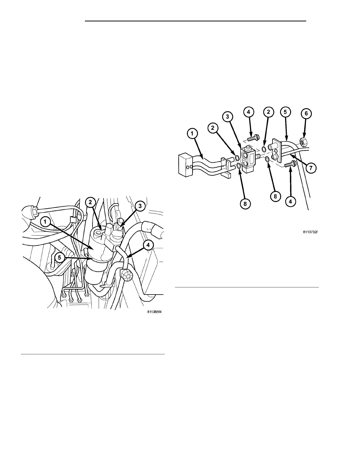
Fig. 17 A/C Expansion Valve
1 - EVAPORATOR TUBE TAPPING PLATE
2 - O-RING SEAL (2)
3 - A/C EXPANSION VALVE
4 - BOLT (2)
5 - A/C SUCTION LINE
6 - NUT
7 - A/C LIQUID LINE
8 - O-RING SEAL (2)
24 - 78 PLUMBING VA