The receiver/drier can not be r epair ed. If th e receiv-
er/drier is fau lty or da maged, or if an in tern al failu re
of th e A/C compressor has occurr ed, the receiver /dr ier
must be r eplaced.
REMOVAL
WARNING: Refer to the applicable warnings and
cautions for this system before performing the fol-
lowing operation (Refer to 24 - HEATING & AIR
CONDITIONING/PLUMBING - WARNINGS) and (Refer
to 24 - HEATING & AIR CONDITIONING/PLUMBING -
CAUTIONS). Failure to follow the warnings and cau-
tions could result in possible personal injury or
death.
(1) Recover th e refriger ant from th e refriger ant
system (Refer t o 24 - HEATING & AIR CONDITION-
ING/PLUMBING - STANDARD PROCE DURE -
REFRIGERANT SYSTEM RECOVE RY).
(2) Remove the bolts that secu re th e front and r ear
section s of the A/C liquid line to the top of th e receiv-
er/drier (Fig. 18).
(3) Disconn ect th e liquid line fittings from t he
receiver/drier an d rem ove a nd discard the O-r ing
seals.
(4) In st all a plug in, or ta pe over the open ed liqu id
lin e fitt ings and t he receiver/drier ports.
(5) Loosen the cla mp th at secures the receiver/
dr ier to the m ounting bracket.
(6) Remove the r eceiver/drier from t he engine com -
part ment .
INSTALLATION
NOTE: If the receiver/drier is being replaced, add 30
milliliters (1 fluid ounce) of refrigerant oil to the
refrigerant system. Use only refrigerant oil of the
type recommended for the A/C compressor in the
vehicle.
(1) Position the receiver/drier onto t he mounting
bracket on th e front left stru t tower.
(2) Tighten the clamp that secures th e receiver/
dr ier to the m ounting bracket.
(3) Remove the tape or plugs from the liquid lin e
fittings and the receiver/drier por ts.
(4) Lubricate new rubber O-r ing seals wit h clea n
refriger ant oi l an d insta ll t hem on the liquid line fit-
tings.
(5) Connect the front and r ear sections of the liq-
uid line to the receiver/drier.
(6) In st all the bolts tha t secures th e liquid line fit-
tings to the receiver/drier. Tighten th e bolts to 7 N·m
(62 in . lbs.).
(7) Eva cuate the refrigera nt system (Refer to 24 -
HEATING & AIR CONDITIONING/PLUMBING -
STANDARD PROCEDURE - REFRIGE RANT SYS-
TEM EVACUATE).
(8) Char ge the refrigera nt system (Refer t o 24 -
HEATING & AIR CONDITIONING/PLUMBING -
STANDARD PROCEDURE - REFRIGE RANT SYS-
TEM CH ARGE).
REFRI GERAN T
DESCRIPTION
The refriger ant used in t his a ir conditionin g sys-
tem is a HydroFluoroCarbon (H FC), type R-134a.
Unlike R-12, which is a ChloroFluoroCa rbon (CFC),
R-134a refrigerant does not contain ozone-depleting
chlorine. R-134a refrigera nt is a non -toxic, non -flam-
mable, clear, and colorless liquefied gas.
Even though R-134a does n ot conta in ch lorine, it
must be reclaimed a nd recycled ju st like CFC-type
refriger ants. This is because R-134a is a gr eenhou se
gas a nd can cont ribu te to globa l warmin g.
OPERATION
R-134a refriger ant is not compat ible with R-12
refriger ant in an a ir con ditionin g system . E ven a
sm all am ount of R-12 a dded t o an R-134a r efrigera nt
system will cau se compressor failure, refrigera nt oil
sludge or poor air conditioning system per formance.
In addition, the PolyAlkylene Glycol (PAG) synthetic
refriger ant oils used in an R-134a r efrigera nt system
are not compa tible with the min eral-based refriger-
ant oils used in an R-12 r efrigera nt system.
R-134a refrigerant system service ports, service
tool couplers a nd refrigera nt dispen sing bott les h ave
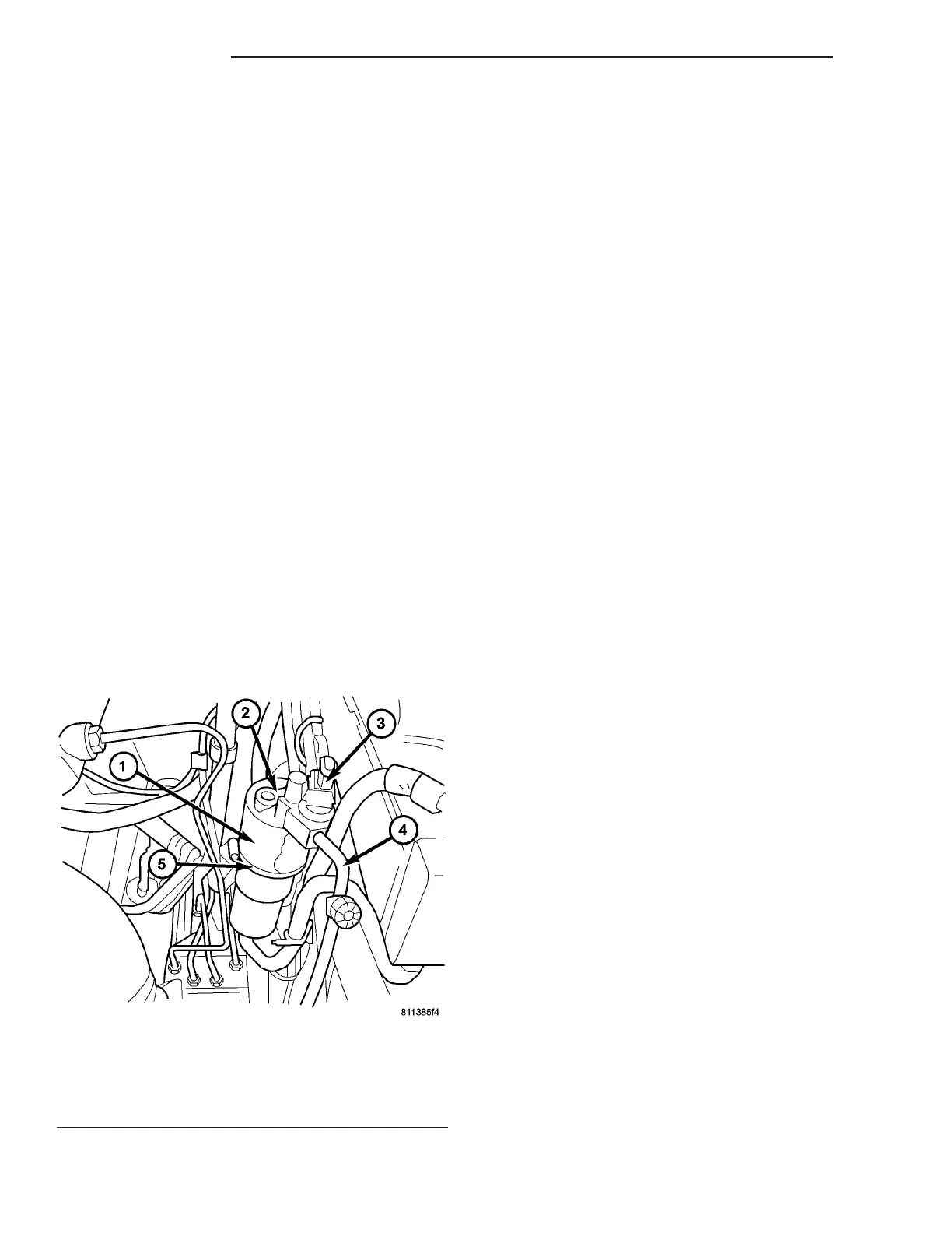
Fig. 18 Receiver/Drier
1 - RECEIVER/DRIER
2 - A/C LIQUID LINE (REAR SECTION)
3 - A/C PRESSURE TRANSDUCER
4 - A/C LIQUID LINE (FRONT SECTION)
5 - CLAMP
24 - 80 PLUMBING VA