(6) Disconn ect the A/C suct ion and liqu id lin es
from the A/C expan sion valve and remove and dis-
card the O-ring seals.
(7) In st all plugs in, or tape over the open ed liqu id
and su ction line fitt ings an d both expa nsion valve
por ts.
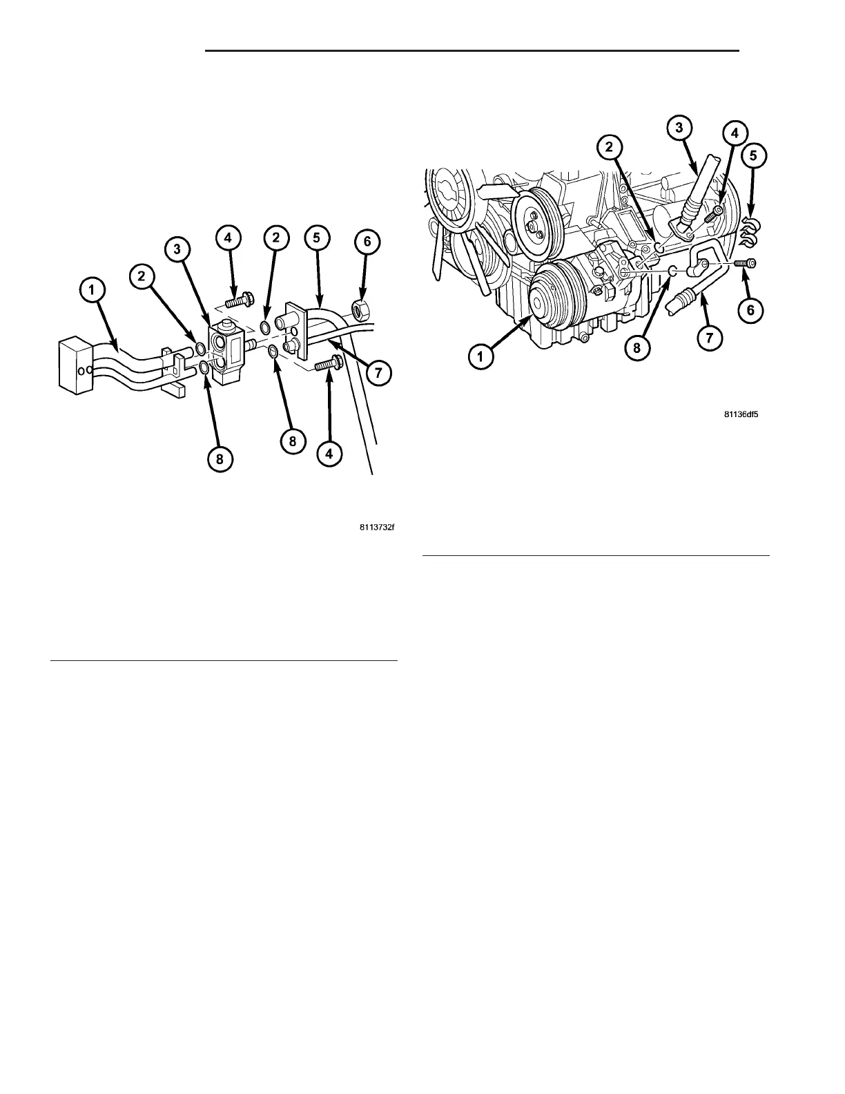
(8) Remove the bolt th at secu res the A/C suction
lin e to the A/C compressor (F ig. 20).
(9) Disconn ect the A/C suction line from t he A/C
compressor an d r emove and disca rd the O-ring sea l.
(10) Install plugs in , or tape over the opened suc-
tion line fitt ing and t he compr essor suct ion port.
(11) Remove the A/C suction line from the en gine
compart ment .
INSTALLATION
(1) Position the A/C suction line into t he engine
compart ment .
(2) Remove plugs or t ape fr om t he su ction lin e fit-
ting and t he compressor suct ion port.
(3) Lubricate a new rubber O-rin g seal with clean
refriger ant oil and install it onto th e su ction lin e fit-
ting.
(4) Connect the A/C suct ion line to the A/C com-
pr essor.
(5) In st all the bolt t hat secu res th e A/C su ction
lin e to t he A/C com pr essor. Tight en the bolt to 23
N·m (17 ft. lbs.).
(6) Remove the tape or plugs from the liquid and
su ction line fitt ings and bot h expansion valve por ts.
(7) Lubricate new rubber O-r ing seals wit h clea n
refriger ant oil an d insta ll them on t he liquid and su c-
tion line fitt ings.
(8) Connect the A/C liquid a nd suction lines to th e
A/C expansion va lve.
(9) In st all the n ut tha t secures the A/C liqu id and
su ction lines t o t he A/C expansion va lve. Tigh ten t he
nut to 10 N·m (89 in . lbs.).
(10) Posit ion the metal routing clip aroun d th e A/C
su ction line and inst all the r outin g clip onto the body
stud.
(11) In st all th e rou tin g clip r etainin g n ut. Tighten
the n ut to 5 N·m (45 in. lbs.).
Fig. 19 A/C Expansion Valve
1 - EVAPORATOR TUBE TAPPING PLATE
2 - O-RING SEAL (2)
3 - A/C EXPANSION VALVE
4 - BOLT (2)
5 - A/C SUCTION LINE
6 - NUT
7 - A/C LIQUID LINE
8 - O-RING SEAL (2)
Fig. 20 A/C Compressor - Refrigerant Lines
1 - A/C COMPRESSOR
2 - O-RING SEAL
3 - A/C SUCTION LINE
4 - BOLT
5 - RETAINING CLIP
6 - BOLT
7 - A/C DISCHARGE LINE
8 - O-RING SEAL
24 - 82 PLUMBING VA