(12) Install t he plastic r outin g clip ret ain er onto
the A/C suction lin e.
(13) Reconn ect the n egative battery cable.
(14) Eva cuat e the refr iger ant system (Refer to 24 -
HEATING & AIR CONDITIONING/PLUMBING -
STANDARD PROCEDURE - REFRIGE RANT SYS-
TEM EVACUATE).
(15) Charge th e refrigerant system (Refer to 24 -
HEATING & AIR CONDITIONING/PLUMBING -
STANDARD PROCEDURE - REFRIGE RANT SYS-
TEM CH ARGE).
WATER V A LVE
REMOVAL
(1) Disconn ect and isolate the negat ive ba tter y
cable.
(2) Partially drain the engine coolin g system
(Refer to 7 - COOLING/ENGINE/COOLANT - STAN-
DARD PROCEDURE - DRAINING COOLING SYS-
TEM).
(3) Disconn ect the wire ha rness connector from th e
heat er water valve (F ig. 21).
(4) Loosen t he hose cla mps fr om th e h eater wa ter
valve .
(5) Usin g a t wisting mot ion gently r emove th e
heat er hoses from the hea ter water valve.
(6) Remove the bolts th at secu re t he h eater wat er
valve bracket.
(7) Remove t he bracket and pu lsed wa ter control
valve fr om the engine com pa rtment.
(8) Turn th e bracket sligh tly an d rem ove the water
valve fr om the r ubber mounts.
(9) If necessary, remove the r ubber mounts from
the bracket or water valve.
INSTALLATION
(1) If rem oved, insta ll the ru bber mounts to the
heat er water valve or bracket.
(2) Turn bracket slightly to the r igh t and install
the h eater water valve t o the bracket.
(3) In st all the water va lve and mountin g br acket
into the engine com pa rtmen t.
(4) In st all the two bracket r etaining bolts. Tigh ten
the bolts t o 5 N·m (45 in . lbs.).
(5) Usin g a twist ing motion gently install th e
heat er hoses onto the water valve.
(6) Tighten t he hose clam ps securely.
(7) Connect th e wire harness con nector to the
heater water valve.
(8) Reconnect t he negat ive batt ery cable.
(9) Fill the engine cooling syst em (Refer to 7 -
COOLING/ENGINE/COOLANT - STANDARD PRO-
CEDURE - COOLING SYSTEM FILL).
REAR A / C CON DEN SER FAN
REMOVAL
(1) Disconn ect and isolate the negat ive ba tter y
cable.
(2) Remove the cover from the r ear A/C condenser
housin g (Refer to 24 - H EATING & AIR CONDI-
TIONING/DISTRIBUTION - REAR/A/C CON-
DENSER COVE R - REMOVAL).
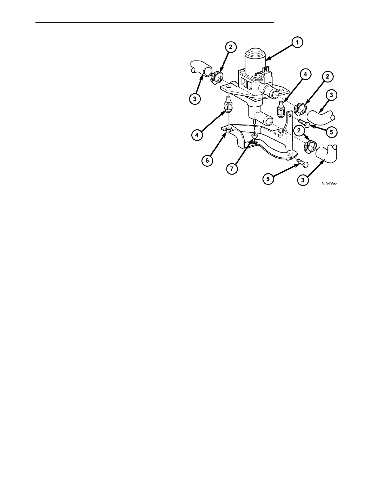
Fig. 21 Heater Water Valve
1 - HEATER WATER VALVE
2 - HOSE CLAMP (3)
3 - HEATER HOSE (3)
4 - RUBBER MOUNT (2)
5 - BOLTS (2)
6 - BRACKET
7 - RUBBER MOUNT
VA PLUMBING 24 - 83