INSTALLATION
(1) Remove the ta pe or plugs from the rea r dis-
charge and un derbody line fittings a nd the rear con-
denser t ube.
(2) Lubricate new O-ring seals with clean refriger-
ant oil and insta ll them onto the rea r discha rge lin e
fittings. Use on ly the specified O-ring sea ls a s they
are made of a specia l ma terial for the R-134a system.
Use only refriger ant oil of the type r ecommen ded for
the r ear A/C compressor in t he vehicle.
(3) From u nderneath the vehicle, route t he rear
A/C discha rge line int o the cargo compa rtment and
insta ll it into the two ret ain ing clips located under
the vehicle.
(4) Connect the rear A/C dischar ge line to the
underbody discha rge lin e. Tight en the nut to 35 N·m
(26 ft. lbs.).
(5) In st all th e foam ru bber seal in to the floor
panel.
(6) From inside the vehicle, in st all t he rear A/C
dischar ge line in to the two r etainin g clips loca ted on
the inner quarter panel and route the discharge line
through th e openin g in t he roof.
(7) Seat the gromm et to the r oof pa nel a nd insta ll
a new rea r A/C wire h arness r etaining st rap.
(8) In st all the thr ee foam insulator s to t he right
inne r q uarte r p ane l.
(9) In st all the r ight quarter trim pan el (Refer to
23 - BODY/INTERIOR/QUARTER TRIM PANEL -
INSTALLATION).
(10) Connect the rear dischar ge lin e to t he rear
A/C conden ser. Tighten the nu t to 35 N·m (26 ft.
lbs.).
(11) In st all t he bracket an d screw th at secures the
rear discha rge line t o the righ t side of the rea r con-
denser housing. Tighten t he screw securely.
(12) Reconn ect the n egative battery cable.
(13) Eva cuat e th e rear refriger ant system (Refer t o
24 - HEATING & AIR CONDITIONING/P LUMBING
- STANDARD PROCEDURE - REFRIGERANT SYS-
TEM EVACUATE).
(14) Charge th e rear refr iger ant syst em (Refer to
24 - HEATING & AIR CONDITIONING/P LUMBING
- STANDARD PROCEDURE - REFRIGERANT SYS-
TEM CH ARGE).
(15) Install the cover onto the rea r A/C evaporator
housin g (Refer to 24 - H EATING & AIR CONDI-
TIONING/DISTRIBUTION - REAR/A/C EVAPORA-
TOR COVE R-REAR - INSTALLATION).
(16) Install t he cover onto the rear A/C condenser
housin g (Refer to 24 - H EATING & AIR CONDI-
TIONING/DISTRIBUTION - REAR/A/C CON-
DENSER COVE R - INSTALLATION).
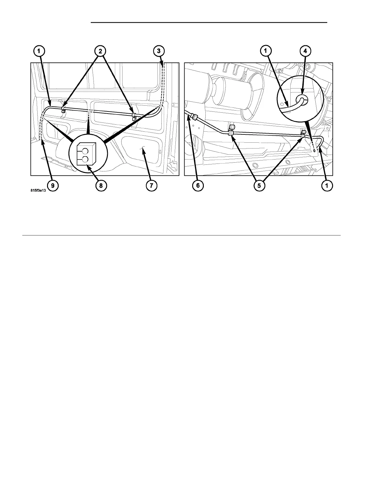
Fig. 29 Rear A/C Discharge Line to Underbody
1 - REAR A/C DISCHARGE LINE
2 - RETAINING CLIPS
3 - TO REAR CONDENSER
4 - FOAM RUBBER SEAL
5 - BRACKETS
6 - UNDERBODY DISCHARGE LINE
7 - RIGHT INNER QUARTER PANEL
8 - FOAM INSULATORS
9 - TO UNDERBODY
24 - 90 PLUMBING VA