(4) Position the t wo spa cer washer s between the
body a nd th e ru bber grommet s for t he two mountin g
points on th e rail.
(5) Tighten t he remaining M6 fasteners to 7 N·m
(62 in. lbs.) an d th e M8 fa st eners to 23 N·m (17 ft.
lbs.) which m ount t he exha ust tube assembly to the
vehicle.
(6) In st all the seat hex nut a t t he heater mounting
flan ge t o t he crossmembers. Tigh ten t he n ut to 60
N·m (44 ft. lbs.)
(7) In st all t he flexible section of th e ca bin heater
exh a u st t u be t o t h e exh a u st t u be. Tigh t en t h e M6
bolt of the cla mp secu rley. Install th e hose to the
exh a u st t u be.
(8) Tighten the two M8 fasten ers a t the ra il to 23
N·m (17 ft. lbs.). Taking care so t hat the exha ust
tube bracket ta b is on th e top of the hea ter bra cket .
(9) In st all th e wir ing ha rness (Refer to 24 - HE AT-
ING & AIR CONDITIONING/CABIN HEATER/
HEATER UNIT - INSTALLATION - WIRE
HARNESS).
(10) Tighten the hose an d t ube assembly to the
toe-board crossmember at two locations.
(11) In st all t he second hose to the underbody hose
and tube assembly.
(12) Connect the rubber fuel hose between the
body tu be assembly a nd the fu el pum p nipple at the
body tu be joint . Close the fuel fill ca p.
(13) Remove th e cabin heater support device from
under the veh icle.
(14) Lower th e veh icle.
(15) Fill the engine cooling syst em (Refer to 7 -
COOLING - STANDARD P ROCEDURE - COOLING
SYSTEM F ILL).
(16) Ver ify fu nction of the heater unit.
WIRE HARNESS
(1) Carefully route the cabin h eater wire ha rness
from the left side between the heater unit and th e
heater shield.
(2) In st all th e two wiring har ness retainers to the
cabin h eater sh ield.
(3) Route the wirin g harn ess along the un der side
of t he vehicle and install the two wiring ha rness
reta iner s t o the under body.
(4) Connect the two cabin hea ter wire ha rness con-
nector s t o the cabin heat er contr oller.
(5) Connect the cabin hea ter wire harn ess to the
dosing pu mp.
(6) Connect the cabin heater wire ha rness con nec-
tor to t he vehicle wirin g ha rness.
(7) Lower th e vehicle.
(8) Verify function of the h eater unit.
INLET HOSE
REMOVAL
NOTE: The air intake tube for the supplemental
cabin heater is part of an assembly that includes
the heater cooling intake and return pipes. If the
cabin heater air intake tube requires removal or
replacement the entire cabin heater assembly will
require removal or replacement.
(1) Drain th e engine cooling system (Refer to 7 -
COOLING - STANDARD PROCE DURE - DRAINING
COOLING STSTEM).
(2) Remove cla mps from th e cabin hea ter tu bes at
the lower heater port a nd the lower EGR connect or
which a re located u nder the hood.
(3) Remove the retaining clamp at th e cabin
heat er air in take muffler conn ection (Refer t o 24 -
HEATING & AIR CONDITIONING/CABIN HEAT-
ER/INLET MUFF LER - REMOVAL).
(4) Remove th e cla mp at the flexible tube to steel
tube connect ion (Fig. 4).
(5) Remove the t wo retaining screws and remove
pipe assembly (F ig. 5).
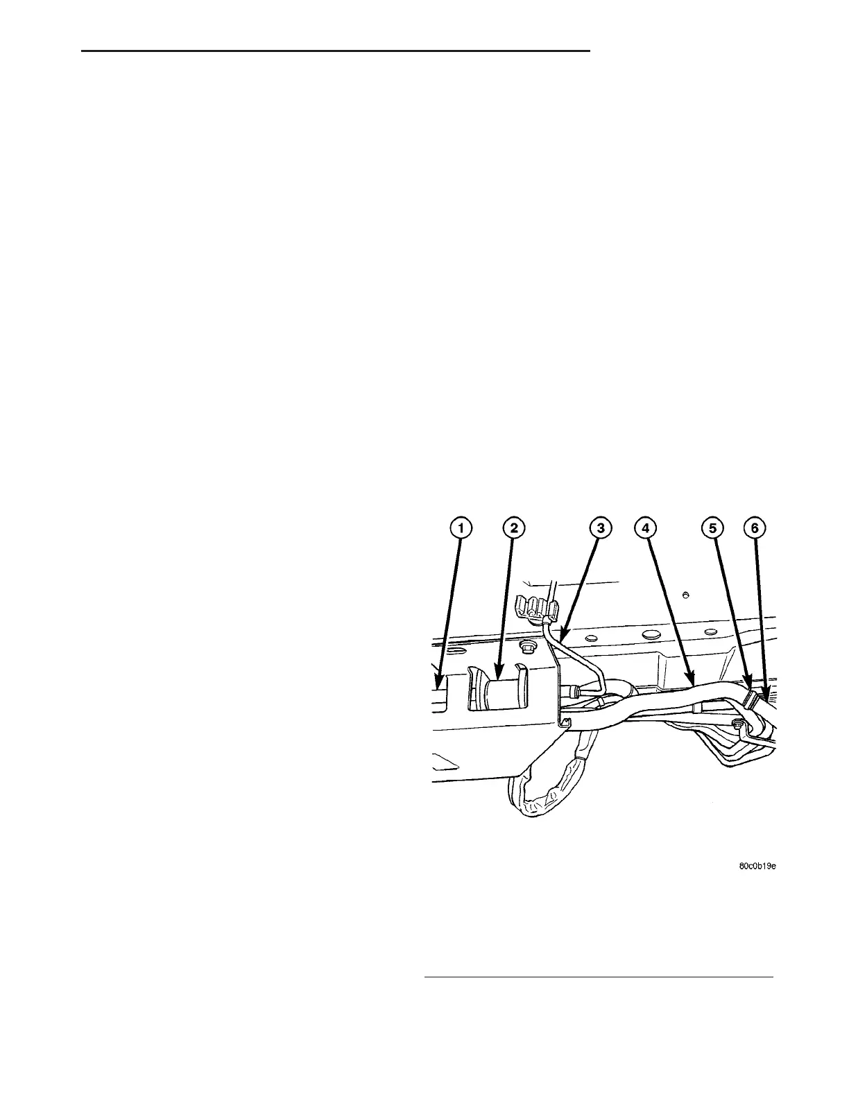
Fig. 4 Cabin Heater Flexible Air Intake Line
1 - CABIN HEATER AND SPLASH SHIELD
2 - DOSING PUMP
3 - DOSING PUMP FUEL LINE
4 - FLEXIBLE INTAKE LINE
5 - CLAMP
6 - STEEL INTAKE PIPE
VA CABIN HEATER 24 - 111