INSTALLATION
(1) In st all t he air inta ke pipe assembly an d in st all
the two reta ining screws. Tighten the screws to 7
N·m (62 in. lbs.).
(2) Attach t he steel tube to the flexible tube and
position and then tighten the retainin g clam p
securely.
(3) In st all t he flexible tube t o the cabin heat er air
intake mu ffler and insta ll a nd tighten t he reta ining
clam p secu rely.
(4) In st all th e cabin heater tubes to the lower
heat er connect ion and t he lower EGR cooler connec-
tion and tighten the reta ining clam ps.
(5) Lower th e vehicle.
(6) Refill th e engine cooling system (Refer to 7 -
COOLING - STANDARD P ROCEDURE - COOLING
SYSTEM F ILL).
(7) Verify function of the h eater unit.
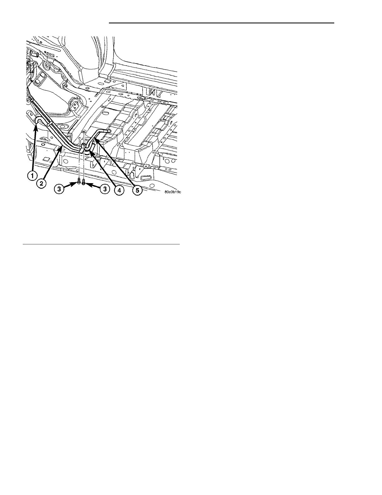
Fig. 5 Cabin Heater Air Intake And Heater Pipe
Assembly
1 - INTAKE TUBE AIR INTAKE
2 - INTAKE PIPE
3 - RETAINING SCREWS
4 - INTAKE HEATER LINE
5 - RETURN HEATER LINE
24 - 112 CABIN HEATER VA