HUB / BEARING
DIAGNOSIS AND TESTING -
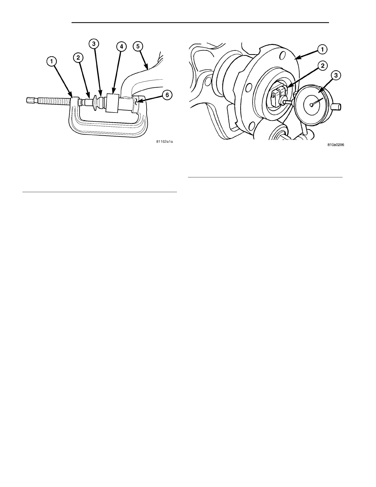
(1) Raise and support the vehicle.
(2) Remove the grea se cap.
(3) Position a dia l indicator against the face of the
wheel hub (Fig. 3).
(4) Tighten t he lockin g screw on the clam ping nut
(Fig. 3).
(5) Pull t he wheel hu b firmly back and forth and
read off the wheel bearing play on the dial gauge.
(Wheel bearing play shou ld be 0.02 - 0.04 mm
(0.000787 - 0.00158 in.).
(6) If necessary, loosen the locking screw and
adju st the wheel bearing pla y by loosing or tight en-
ing the clamping nut .
(7) Retight en the locking screw and recheck the
wh eel bea r in g pla y.
REMOVAL
(1) Raise and support the vehicle.
(2) Remove t he front wheels (Refer to 22 - TIRES/
WHEELS/WHEELS - RE MOVAL).
(3) Remove th e disc brake caliper ada pt er (Refer to
5 - BRAKES/HYDRAULIC/MECH ANICAL/DISC
BRAKE CALIPE R ADAPTE R - REMOVAL).
(4) Remove the wheel fla nge ring (if equ ipped wit h
du al r ear wheels) (F ig. 5).
(5) Remove the disc brake rotor (Refer to 5 -
BRAKES/HYDRAULIC/MECHANICAL/ROTORS -
REMOVAL).
(6) Remove the grea se cap (Fig. 4).
(7) Loosen the bolt on the cla mping nut a nd
remove th e clamping nut (F ig. 4).
(8) Remove the thrust washer (F ig. 4).
(9) Remove t he wheel hub and taper ed roller bea r-
ing from th e stub axle assem bly (Fig. 4).
Fig. 2 LCA BUSHING INSTALL
1 - SPECIAL TOOL C-4212F (PRESS)
2 - SPECIAL TOOL 9302-1 (DRIVER)
3 - BUSHING
4 - SPECIAL TOOL 9302-2 (SIZER CUP)
5 - LOWER CONTROL ARM
6 - SPECIAL TOOL 9302-4 (RECEIVER CUP)
Fig. 3 MEASURING & ADJUSTING WHEEL BEARING
1 - WHEEL HUB
2 - LOCKING SCREW
3 - DIAL INDICATOR
2-4 FRONT VA