INSTALLATION
(1) In st all the wh eel hu b with th e tapered roller
bearing on the st ub axle (Fig. 4).
(2) Grease t he outer tapered roller bearing th or-
oughly a nd push onto the st eerin g knuckle (Fig. 4).
NOTE: The smooth side of the thrust washer must
point toward the wheel bearing.
(3) In st all the thr ust washer (Fig. 4).
(4) In st all the clam ping nut (Fig. 4). Tighten to 12
N·m (9 ft . lbs.) a nd then loosen a ha lf of a turn.
(5) Check for wheel bearing en d pla y. End play
sh ould be 0.02- 0.04 mm (0.000787 - 0.00158 in.)
(Fig. 3) (Refer to 2 - SUSPE NSION/FRONT/HUB /
BEARING - DIAGNOSIS AND TESTING).
(6) Pack the grea se cap ha lf with grease and coat
at the edge with seala nt and install t he cap (Fig. 4).
(7) In st all the disc brake rotor (Refer to 5 -
BRAKES/HYDRAULIC/MECHANICAL/ROTORS -
INSTALLATION).
(8) In st all th e disc brake ca liper adapter (Refer to
5 - BRAKES/HYDRAULIC/MECH ANICAL/DISC
BRAKE CALIPE R ADAPTE R - INSTALLATION).
(9) In st all th e wheel flange ring (if equipped with
du al r ear wheels) (F ig. 5).
(10) Install the fr ont tire & wheels assembly
(Refer to 22 - TIRES/WH EELS/WHEE LS - INSTAL-
LATION).
(11) Lower th e vehicle.
KNUCKLE
REMOVAL
(1) Raise and support the vehicle.
(2) Remove t he front wheels (Refer to 22 - TIRES/
WHEELS/WHEELS - RE MOVAL).
(3) Remove th e disc brake caliper ada pt er (Refer to
5 - BRAKES/HYDRAULIC/MECH ANICAL/DISC
BRAKE CALIPE R ADAPTE R - REMOVAL).
(4) Remove the h ub/bea ring (Refer to2-SUSPEN-
SION/FRONT/HUB / BEARING - REMOVAL).
(5) Sepa rat e the out er tie rod from th e st eering
knu ckle (Fig. 6) using specia l tool C-3894–A.
(6) Raise the lower control arm approxima tely 10
mm using a jack. In o rd e r t o el imi n a t e t e n s i le
fo rc e i n t h e d a m p er s t rut .
(7) Remove the ABS sensor fr om the knuckle by
pu lling st raight ou t.
(8) Remove the st rut at t he knuckle (Fig. 6).
(9) Sepa rat e the lower ball joint from the steer ing
knu ckle using special tool 9282 (Fig. 6).
(10) Remove t he st eering kn uckle from the vehicle
(Fig. 6).
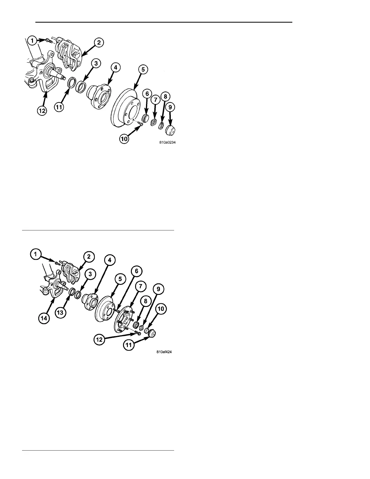
Fig. 4 FRONT WHEEL HUB WITH SINGLE REAR
WHEELS (SRW)
1 - CALIPER ADAPTER BOLT
2 - DISC BRAKE CALIPER
3 - INNER BEARING
4 - WHEEL HUB
5 - DISC BRAKE ROTOR
6 - OUTER BEARING
7 - THRUST WASHER
8 - CLAMPING NUT
9 - GREASE CAP
10 - LOCKING BOLT
11 - GREASE SEAL
12 - STEERING KNUCKLE
Fig. 5 FRONT WHEEL HUB WITH DUAL REAR
WHEELS (DRW)
1 - ADAPTER BOLT
2 - DISC BRAKE CALIPER
3 - INNER BEARING RACE
4 - WHEEL HUB
5 - DISC BRAKE ROTOR
6 - LOCKING BOLT
7 - WHEEL FLANGE RING
8 - OUTER BEARING
9 - THRUST WASHER
10 - CLAMPING NUT
11 - GREASE CAP
12 - WHEEL FLANGE RING MOUNTING BOLT
13 - GREASE SEAL
14 - STEERING KNUCKLE
VA FRONT 2 - 5