INSTALLATION
(1) In st all the st eering knuckle on t he lower ball
joint stud (F ig. 6).
(2) In st all th e lower ball joint nut (Fig. 6). Tigh ten
to 280 N·m (206 ft. lbs.)
(3) In st all th e strut to th e steerin g knu ckle (Fig.
6). Tighten t o 185 N·m (136 ft . lbs.).
(4) In st all the outer tie rod end to th e steerin g
knu ckle (Fig. 6) and tigh ten the nu t to 130 N·m (96
ft. lbs.).
(5) In st all the ABS sensor by pushing the sen sor
all the way into t he knuckle a nd the sen sor will self
adjust when the wheel is turned.
(6) In st all the h ub/bea rin g (Refer to2-SUSPEN-
SION/FRONT/HUB / BEARING - INSTALLATION).
(7) In st all the disc brake ca liper ada pter with the
brake caliper (Refer to 5 - BRAKES/HYDRAULIC/
MECHANICAL/DISC BRAKE CALIPE R ADAP TER -
INSTALLATION).
(8) In st all the front wheels (Refer to 22 - TIRES/
WHEELS/WHEELS - INSTALLATION).
(9) Lower th e vehicle.
(10) Check a nd set toe if necessary (Refer to 2 -
SUSPENSION/WHE EL ALIGNMENT - STANDARD
PROCE DURE ).
LOWER BALL J OI N T
REMOVAL
(1) Raise and support the vehicle.
(2) Remove the front tire and wh eel a ssem bly.
(3) Remove the front strut (Refer to2-SUSPEN-
SION/FRONT/STRUT - REMOVAL).
(4) Remove the steering knuckle (Refer to2-SUS-
PENSION/F RONT/KNUCKLE - REMOVAL).
(5) Remove the lower ba ll joint using special tool
9294-1 (Driver) with 9294-2 (Reciever) and C-4212–F.
(Fig. 7).
INSTALLATION
(1) In st all the ba ll join t int o th e lower con trol arm
using special tool 9294-3 (In st aller ring) insert ed in
9294-2 (Reciever) a nd C-4212–F (Fig. 7).
(2) In st all the front str ut (Refer to2-SUSPEN-
SION/FRONT/STRUT - INSTALLATION).
(3) In st all the steerin g knu ckle (Refer to2-SUS-
PENSION/F RONT/KNUCKLE - INSTALLATION).
(4) In st all t he tire and wheel assembly (Refer to 22
- TIRES/WHEELS/WHEELS - INSTALLATION).
(5) Lower th e vehicle.
(6) Check the front wheel alignment (Refer to 2 -
SUSPENSION/WHE EL ALIGNMENT - SP ECIFICA-
TIONS).
LOWER CON T ROL ARM
REMOVAL
(1) In sert sprin g blocks special tool 9288 bet ween
the spring a nd the sprin g cla mp plates, While the
vehicles wheels are on the ground.
(2) Raise and support the vehicle.
(3) Remove t he front wheels (Refer to 22 - TIRES/
WHEELS/WHEELS - RE MOVAL).
(4) Remove th e disc brake caliper ada pt er (Refer to
5 - BRAKES/HYDRAULIC/MECH ANICAL/DISC
BRAKE CALIPER ADAP TER - REMOVAL). Hang
the caliper. Do not allow brake hose to support
the caliper w eight.
(5) Remove the retaining nu t h olding the tie rod to
the st eering knu ckle (Fig. 8).
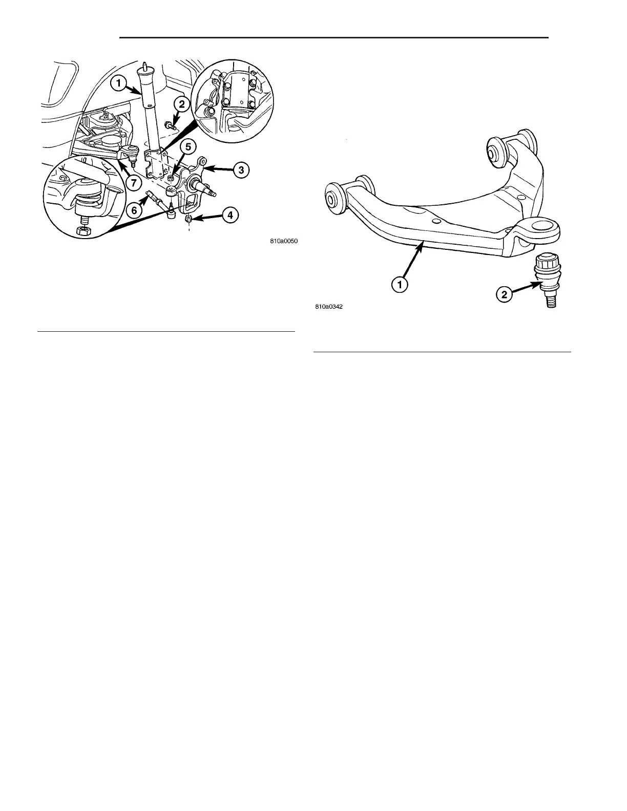
Fig. 6 STEERING KNUCKLE
1 - STRUT
2 - STRUT BOLT
3 - STEERING KNUCKLE
4 - LOWER BALL JOINT NUT
5 - OUTER TIE ROD END RETAINING NUT
6 - INNER TIE ROD END
7 - LOWER CONTROL ARM
Fig. 7 LOWER BALL JOINT
1 - LOWER CONTROL ARM
2 - LOWER BALL JOINT
2-6 FRONT VA