(6) Seperat e th e tie rod off the steer ing knuckle
(Fig. 8) using special tool C-3894–A.
NOTE: In order to remove tension from the strut,
Raise the lower control arm approximately 10 mm
with a jack.
(7) Remove the st rut bolts from the steerin g
knu ckle (Fig. 8).
(8) Remove the st op plate bolts and rota te the
plate upwards wit h the stabilizer link a ttached (Fig.
8).
(9) Lower th e lower con trol arm .
(10) Remove the lower ball joint nut from th e
st eering knu ckle (Fig. 8).
(11) Sepa rat e the lower ball joint fr om the kn uckle
using specia l tool 9282.
(12) Remove the lower contr ol arm nu ts a nd bolts
from the fram e (Fig. 8).
(13) Remove th e lower con trol arm .
INSTALLATION
(1) In st all the lower control a rm to the frame.
Hand t ighten the nut s a nd bolt s.
NOTE: In order to remove tension from the strut,
Raise the lower control arm approximately 10 mm
with a jack.
(2) In st all the lower ball join t into the steering
knu ckle. Tight en to 280 N·m (206 ft. lbs.).
(3) In st all the str ut bolt s to the steerin g knuckle
(Fig. 8). Tighten to 185 N·m (136 ft. lbs.).
(4) In st all th e stop pla te (Refer to2-SUSPEN-
SION/FRONT/SP RING STOP PLATES - INSTALLA-
TION).
(5) Lower th e lower con trol arm .
(6) Attach the tie rod to the steer ing kn uckle (F ig.
8). Tighten t he nu t to 130 N·m (96 ft. lbs.)
(7) In st all th e disc brake ca liper adapter (Refer to
5 - BRAKES/HYDRAULIC/MECH ANICAL/DISC
BRAKE CALIPER ADAPTER - INSTALLATION)
(Fig. 8).
(8) In st all the front tire & wh eel a ssembly (Refer
to 22 - TIRE S/WHEE LS/WHE ELS - INSTALLA-
TION).
(9) Lower th e vehicle.
(10) Remove the spring blocks between t he sprin g
and the spring cla mp plates, While th e vehicles
wheels are on the grou nd.
(11) Roll th e vehicle approxima tely 1 mm forwa rds
and the backwards, and r ock firmly.
(12) Tighten the lower contr ol arm nuts an d bolts
to th e frame to 150 N·m (110 ft. lbs.) (F ig. 8).
(13) Apply brake to actuate br ake pressur e.
SPRI N G
REMOVAL
(1) To d o t h i s n e x t s t e p t h e v e h i c le m u s t b e
on the ground. Rem ove th e front and r ear bolts on
the left an d r igh t spring clamp plates (F ig. 9).
(2) Raise and support the vehicle.
(3) Remove the front wh eels.
(4) Remove the br ake caliper adapter (Refer to 5 -
BRAKES/HYDRAULIC/MECHANICAL/DISC
BRAKE CALIPE R ADAPTE R - RE MOVAL). Do not
allow the caliper to hang by the hose, support
th e ca lip e r a c c o rd in g ly.
(5) Remove the ABS sen sor from the mount ing
bore in the st eering knu ckle (Fig. 9).
(6) Remove the outer tie r od reta ining nut and
sepa rat e the tie rod from the knuckle (Fig. 9) using
special tool C-3894–A.
NOTE: In order to remove tension from the strut,
Raise the lower control arm approximately 10 mm
with a jack.
(7) Remove the st rut bolts from the steerin g
knu ckle.
(8) Remove both stop pla te bolts and rotate the
plates u pwards with th e stabilizer link att ached.
(9) Lower th e lower con trol arm .
(10) Remove the lower ball joint nut from th e
st eering knu ckle.
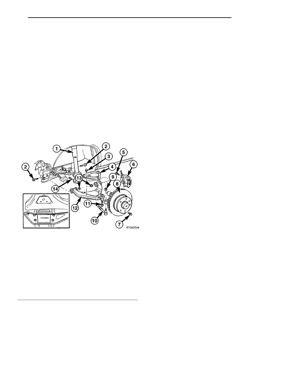
Fig. 8 LOWER CONTROL ARM
1 - STRUT
2 - LOWER CONTROL ARM BOLT
3 - STOP PLATE BOLT
4 - STOP PLATE
5 - CALIPER ADPTER BOLT
6 - DISC BRAKE CALIPER
7 - LOCKING BOLT
8 - DISC BRAKE ROTOR
9 - OUTER TIE ROD END RETAINING NUT
10 - OUTER TIE ROD END
11 - LOWER BALL JOINT NUT
12 - LOWER BALL JOINT
13 - LOWER CONTROL ARM NUTS
14 - STRUT BOLT
VA FRONT 2 - 7