INSTALLATION
(1) In st all the m aster cylinder to th e brake booster
(Fig. 20). Tigh ten to 28 N·m (248 in . lbs.).
(2) In st all the brake lines (Fig. 20). Tight en to 14
N·m (124 in. lbs.).
(3) In st all t he fluid reservoir (Fig. 20) (Refer to 5 -
BRAKES/HYDRAULIC/MECHANICAL/FLUID RES-
ERVOIR - INSTALLATION).
(4) Bleed t he brake system.
(5) Check the br ake system for any leaks.
PEDAL
REMOVAL
(1) Remove the master cylinder (Refer to 5 -
BRAKES/HYDRAULIC/MECHANICAL/MASTE R
CYLINDER - REMOVAL).
(2) Remove th e retainer and pin for the ma st er
cylinder push rod (F ig. 22).
(3) Remove the r etainer an d pin for the brake
peda l pivot bolt (Fig. 22).
(4) Unh ook t he spring an d remove t he brake peda l
(Fig. 22).
(5) Disconn ect the plug connector on t he stop la mp
switch (Fig. 22).
(6) Remove the bolts and remove the peda l bearing
bracket (Fig. 22).
INSTALLATION
(1) In st all the bolts for th e pedal bearing bracket
(Fig. 22). Tigh ten to 23 N·m (204 in . lbs.)
(2) Reconnect th e plug connector for th e st op lamp
switch (Fig. 22).
(3) In st all the br ake pedal and h ook the spr ing
(Fig. 22).
(4) In st all th e ret ainer an d pin for the brake peda l
(Fig. 22).
(5) In st all the r etainer and pin for t he mast er cyl-
inder push rod (F ig. 22).
(6) In st all th e master cylinder (Refer to 5 -
BRAKES/HYDRAULIC/MECHANICAL/MASTE R
CYLINDER - INSTALLATION).
POWER BRAK E BOOST ER
DESCRIPTION
All models use a tandem diaphr agm, power brake
booster.
NOTE: The power brake booster is not a repairable
component. The booster must be replaced as an
assembly if diagnosis indicates a malfunction has
occurred.
OPERATION
The booster un it consists of a sin gle housin g
divided int o two by a tandem diaphr agm . The outer
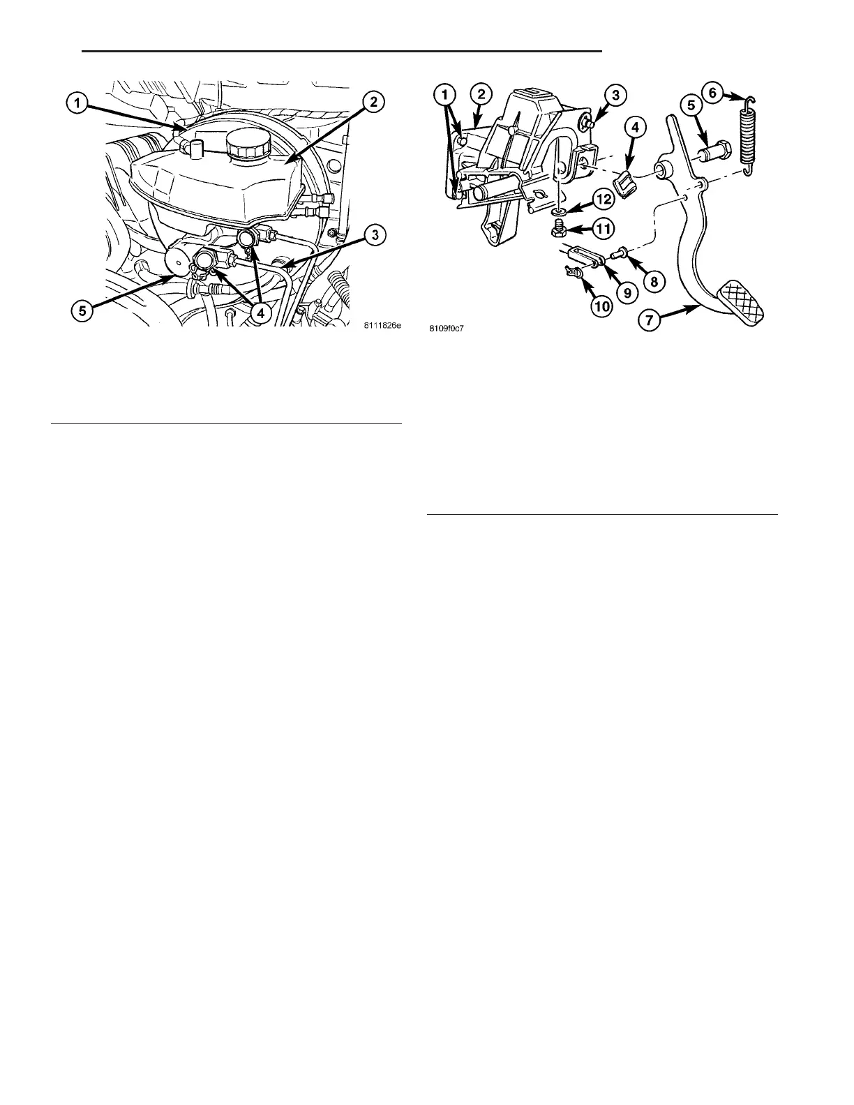
Fig. 21 MASTER CYLINDER (DRW)
1 - POWER BRAKE BOOSTER
2 - RESERVOIR
3 - BRAKE LINES
4 - PRESSURE PORTS
5 - MASTER CYLINDER
Fig. 22 BRAKE PEDAL
1 - MOUNTING BOLT
2 - PEDAL BEARING BRACKET
3 - STOP LAMP SWITCH
4 - CLIP
5 - PIVOT BOLT
6 - RETURN SPRING
7 - PEDAL
8 - PUSH ROD BOLT
9 - PUSH ROD
10 - CLIP
11 - BOLT
12 - WASHER
VA BRAKES - BASE 5 - 19