edge of t he diaphragm is secur ed to the housing. The
booster push rod, which con nects th e booster to the
brake peda l and m aster cylinder, is at tached to the
center of the diaph ragm. A check va lve is used in th e
booster outlet con nected to the engine in take mani-
fold. Power assist is gener ated by ut ilizing a combi-
nation of va cuum and atmospheric pressur e t o boost
br a k e a ssist .
REMOVAL
(1) Usin g a suct ion gu n remove as much brake
fluid from the reservoir as possible.
(2) Disconn ect th e bra ke level switch electrical
connect or.
(3) Remove th e brake lines fr om the ma ster cylin-
der Seal off the ends and bore holes with plugs.
(4) Remove the master cylinder from t he booster.
(5) Remove t he boost er va cuum hose and check
valve (F ig. 23).
(6) Remove the peda l push rod clip (Fig. 23).
(7) Remove the booster mou nting n uts (Fig. 23).
(8) Remove the booster from t he vehicle.
INSTALLATION
(1) In st all the brake booster to th e vehicle.
(2) In st all the booster mountin g nuts (Fig. 23).
Tighten t o 25 N·m (221 in.lbs.).
(3) In st all the push rod pin & clip (Fig. 23).
(4) In st all the brake boost er vacu um line a nd
check valve (Fig. 23).
(5) In st all the master cylinder t o the brake
booster. Tighten to 28 N·m (248 in.lbs.).
(6) In st all the brake lin es to th e m aster cylinder.
Tighten t o 14 N·m (124 in.lbs.).
(7) In st all th e brake level switch electrical conn ec-
tor.
(8) Bleed t he ba se brake syst em (Refer to 5 -
BRAKES - STANDARD PROCE DURE ).
ROT ORS
REM OVAL
REMOVAL - FRONT (SRW)
(1) Raise and support the vehicle.
(2) Remove the front wh eels.
(3) Remove the front br ake pads (Fig. 24).
(4) Remove the caliper adapter (F ig. 24).
(5) In st all two lug studs to secu re the disc bra ke
rotor wh en the locking bolt is removed.
(6) Remove the locking bolt for th e disc bra ke rotor
(Fig. 24).
(7) Remove the two lug nuts.
(8) Remove the disc bra ke r otor (Fig. 24).
REMOVAL - REAR (SRW)
(1) Raise and support the vehicle.
(2) Remove the rear wheels.
(3) Remove the rear disc bra ke pads (Fig. 25).
(4) Remove the disc bra ke ca liper adapter (F ig.
25).
(5) Apply the parking bra ke.
(6) In st all two lug studs to secu re the disc bra ke
rotor wh en the locking bolt is removed.
(7) Remove the locking bolt for th e disc bra ke rotor
(Fig. 25).
(8) Remove the two lug nuts.
(9) Relea se the pa rking bra ke.
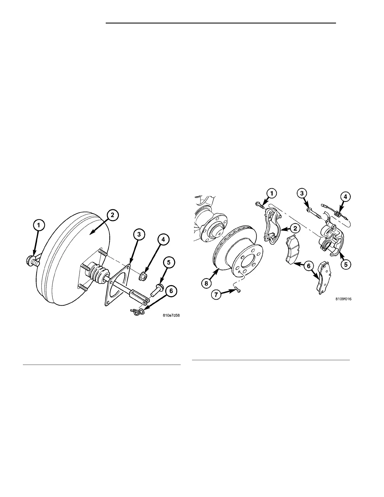
Fig. 23 POWER BRAKE BOOSTER
1 - VACUUM LINE & CHECK VALVE
2 - BRAKE BOOSTER
3 - GASKET
4 - MOUNTING NUTS (4)
5 - PUSH ROD PIN
6 - SECURING CLIP
Fig. 24 FRONT DISC BRAKE ROTOR
1 - CALIPER ADAPTER BOLT
2 - CALIPER ADAPTER
3 - GUIDE BOLT
4 - WEAR INDICATOR
5 - DISC BRAKE CALIPER
6 - DISC BRAKE PADS
7 - LOCKING BOLT
8 - DISC BRAKE ROTOR
5-20 BRAKES-BASE VA