(10) loosen th e park brake adjuster to allow clear-
ance for the r otor removal (Fig. 25).
(11) Remove the rear disc bra ke r otor.
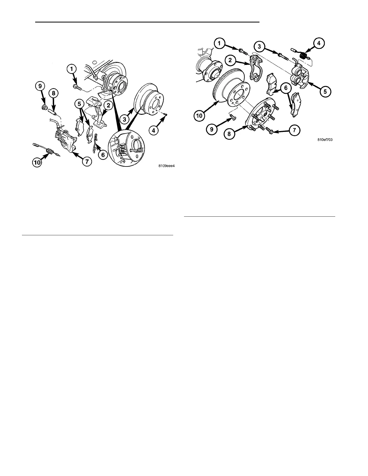
REMOVAL - FRONT (DRW)
(1) Raise and support the vehicle.
(2) Remove the front wh eels.
(3) Remove the front br ake pads (Fig. 26).
(4) Remove the caliper adapter (F ig. 26).
(5) Remove the wheel fla nge r ing (Fig. 26).
(6) In st all two lug studs to secu re the disc bra ke
rotor wh en the locking bolt is removed.
(7) Remove the locking bolt for th e disc bra ke rotor
(Fig. 26).
(8) Remove the two lug nuts.
(9) Remove the disc bra ke r otor (Fig. 26).
REMOVAL - REAR (DRW)
(1) Raise and support the vehicle.
(2) Remove the rear wheels.
(3) Remove the rear disc bra ke pads (Fig. 27).
(4) Remove the disc bra ke ca liper adapter (F ig.
27).
(5) Apply the parking bra ke.
(6) In st all two lug studs to secu re the disc bra ke
rotor wh en the locking bolt is removed.
(7) Remove the wheel fla nge r ing (Fig. 27).
(8) Remove the locking bolt for th e disc bra ke rotor
(Fig. 27).
(9) Remove the two lug nuts.
(10) Release th e parkin g brake.
(11) loosen the par k brake adj u st er to allow clear-
ance for the r otor removal (Fig. 27).
(12) Remove th e rear disc brake rotor.
Fig. 25 REAR DISC BRAKE ROTOR
1 - M8 BOLT
2 - CALIPER ADAPTER
3 - DISC BRAKE ROTOR
4 - LOCKING BOLT
5 - DISC BRAKE PADS
6 - RATTLE SPRING
7 - DISC BRAKE CALIPER
8 - GUIDE BOLT
9 - COVER
10 - WEAR INDICATOR
Fig. 26 FRONT DISC BRAKE ROTOR WITH DUAL
REAR WHEELS
1 - ADAPTER BOLT
2 - ADAPTER
3 - GUIDE PIN/BOLT
4 - WEAR INDICATOR WIRE
5 - DISC BRAKE CALIPER
6 - DISC BRAKE PADS
7 - WHEEL FLANGE RING MOUNTING BOLT
8 - WHEEL FLANGE RING
9 - LOCKING BOLT
10 - DISC BRAKE ROTOR
VA BRAKES - BASE 5 - 21