INSTALLATION
INSTALLATION - FRONT (SRW)
(1) In st all the disc br ake r otor to th e hub an d
insta ll two lug st uds to hold rotor in place.
(2) In st all th e lockin g bolt for t he rotor (Fig. 24).
Tighten t o 23 N·m (204 in. lbs.).
(3) In st all t he disc brake caliper adapter (Fig. 24).
Tighten to 170 N·m (125 ft . l bs.) (Refer to 5 -
BRAKES/HYDRAULIC/MECHANICAL/DISC
BRAKE CALIPE R ADAPTE R - INSTALLATION).
(4) In st all the bra ke pa ds (Refer to 5 - BRAKE S/
HYDRAULIC/ME CHANICAL/BRAKE PADS/SHOE S
- INSTALLATION) (Fig. 24).
(5) Press and release th e br ake peda l sever al times
until pressure has built up.
(6) Check fluid in reservoir and correct if neces-
sary.
(7) In st all the front wheels (Refer to 22 - TIRES/
WHEELS/WHEELS - INSTALLATION).
(8) Lower th e vehicle.
INSTALLATION - REAR (SRW)
(1) In st all the disc br ake r otor to th e hub an d
insta ll two lug st uds to hold rotor in place (Fig. 25).
(2) Apply the parking bra ke.
(3) In st all th e lockin g bolt for t he rotor (Fig. 25).
Tighten t o 23 N·m (204 in. lbs.).
(4) In st all t he disc brake caliper adapter (Fig. 25).
Tighten to 90 N·m (66 ft. lbs.) (Refer to 5 - BRAKES/
HYDRAULIC/ME CHANICAL/DISC BRAKE CALI-
PER ADAPTER - INSTALLATION).
(5) In st all the bra ke pa ds (Refer to 5 - BRAKE S/
HYDRAULIC/ME CHANICAL/BRAKE PADS/SHOE S
- INSTALLATION) (Fig. 25).
(6) Relea se the pa rking bra ke.
(7) Adjust the parking br ake (Refer to 5 -
BRAKES/PARKING BRAKE/SHOES - ADJ UST-
MENTS).
(8) Press and release th e br ake peda l sever al times
until pressure has built up.
(9) Check fluid in reservoir and correct if neces-
sary.
(10) Install the rea r wheels.
(11) Lower th e vehicle.
INSTALLATION - FRONT (DRW)
(1) In st all the disc br ake r otor to th e hub an d
insta ll two lug st uds to hold rotor in place.
(2) In st all th e lockin g bolt for t he rotor (Fig. 26).
Tighten t o 23 N·m (204 in. lbs.).
(3) In st all t he disc brake caliper adapter (Fig. 26).
Tighten to 170 N·m (125 ft . l bs.) (Refer to 5 -
BRAKES/HYDRAULIC/MECHANICAL/DISC
BRAKE CALIPE R ADAPTE R - INSTALLATION).
(4) In st all the wh eel flange ring. Tighten to 180
N·m (133 ft. lbs.)
(5) In st all the bra ke pa ds (Refer to 5 - BRAKE S/
HYDRAULIC/ME CHANICAL/BRAKE PADS/SHOE S
- INSTALLATION) (Fig. 26).
(6) Press and release th e br ake peda l sever al times
until pressure has built up.
(7) Check fluid in reservoir and correct if neces-
sary.
(8) In st all the front wheels (Refer to 22 - TIRES/
WHEELS/WHEELS - INSTALLATION).
(9) Lower th e vehicle.
INSTALLATION - REAR (DRW)
(1) In st all the disc br ake r otor to th e hub an d
insta ll two lug st uds to hold rotor in place (Fig. 27).
(2) Apply the parking bra ke.
(3) In st all th e lockin g bolt for t he rotor (Fig. 27).
Tighten t o 23 N·m (204 in. lbs.).
(4) In st all t he disc brake caliper adapter (Fig. 27).
Tighten to 170 N·m (125 ft . l bs.) (Refer to 5 -
BRAKES/HYDRAULIC/MECHANICAL/DISC
BRAKE CALIPE R ADAPTE R - INSTALLATION).
(5) In st all t he wheel flange ring (Fig. 27) Tigh ten
to 200 N·m (148 ft. lbs.).
(6) In st all the bra ke pa ds (Refer to 5 - BRAKE S/
HYDRAULIC/ME CHANICAL/BRAKE PADS/SHOE S
- INSTALLATION) (Fig. 27).
(7) Relea se the pa rking bra ke.
(8) Adjust the parking br ake (Refer to 5 -
BRAKES/PARKING BRAKE/SHOES - ADJ UST-
MENTS).
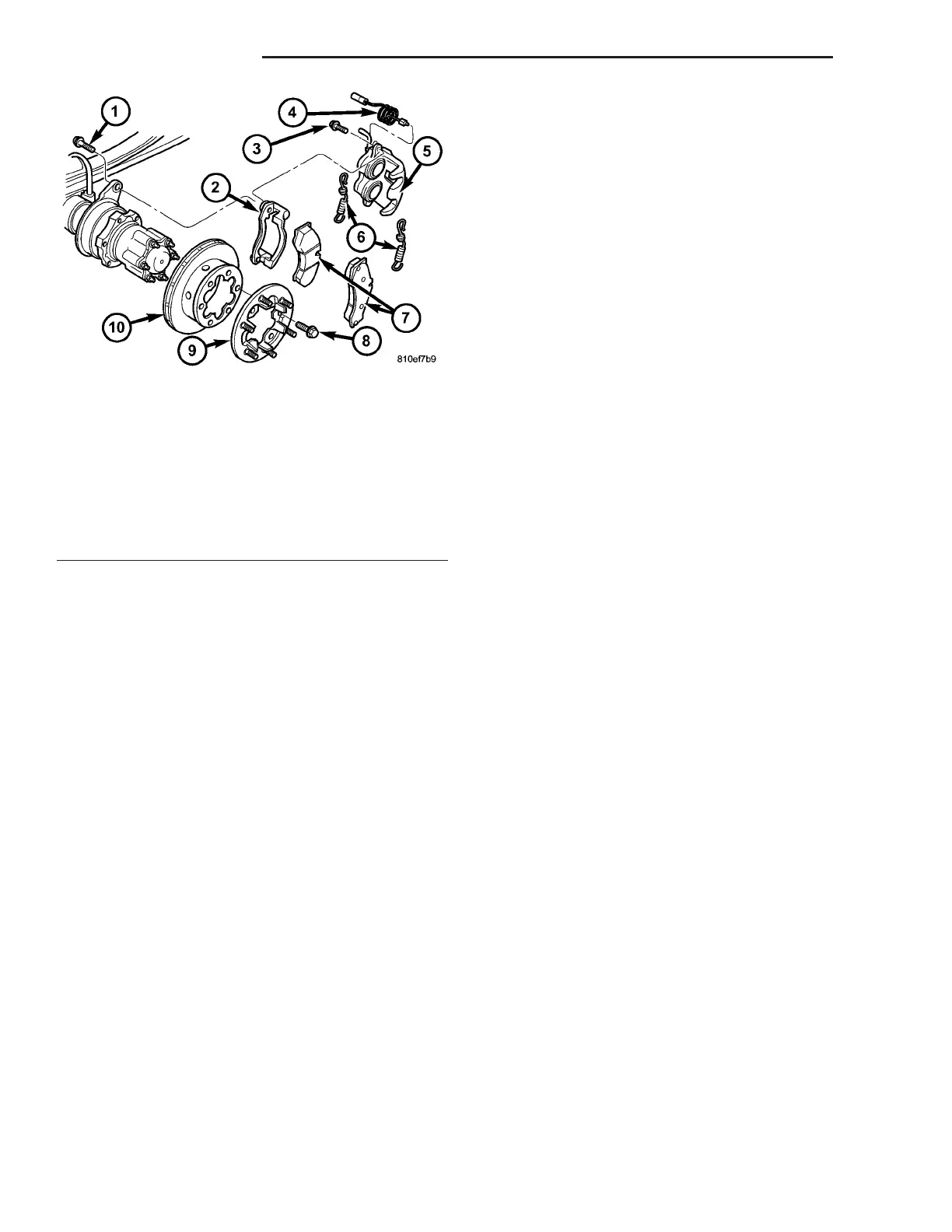
Fig. 27 REAR DISC BRAKE ROTOR WITH DUAL
REAR WHEELS
1 - ADAPTER BOLT
2 - ADAPTER
3 - GUIDE PIN/BOLT
4 - WEAR INDICATOR
5 - DISC BRAKE CALIPER
6 - RETAINING SPRING
7 - DISC BRAKE PADS
8 - WHEEL FLANGE RING MOUNITNG BOLT
9 - WHEEL FLANGE RING
10 - DISC BRAKE ROTOR
5-22 BRAKES-BASE VA