(9) Press and release th e br ake peda l sever al times
until pressure has built up.
(10) Check fluid in reservoir and cor rect if neces-
sary.
(11) In st all the rear wh eels.
(12) Lower th e veh icle.
SU PPORT PLAT E
REMOVAL - REAR
(1) Raise and support the vehicle.
(2) Remove th e disc brake caliper ada pt er (Refer to
5 - BRAKES/HYDRAULIC/MECH ANICAL/DISC
BRAKE CALIPE R ADAPTE R - REMOVAL).
(3) Remove the disc brake rotor (Refer to 5 -
BRAKES/HYDRAULIC/MECHANICAL/ROTORS -
REMOVAL).
(4) Remove t he rear par k brake sh oes (Refer to 5 -
BRAKES/PARKING BRAKE/SH OES - REMOVAL).
(5) Remove the park br ake cable from he support
plat e.
(6) Remove the rear axle bearing (Refer t o3-DIF-
FERE NTIAL & DRIVE LINE/REAR AXLE/AXLE
BEARINGS - REMOVAL).
(7) Remove bra ke support plate.
INSTALLATION - REAR
(1) Press the br ake support plate with th e a xle
bearing onto the axle shaft (Refer to3-DIFFEREN-
TIAL & DRIVELINE/REAR AXLE/AXLE BEARINGS
- INSTALLATION).
(2) In st all the pa rk bra ke cable t o t he support
plat e.
(3) In st all the rear pa rk brake shoes (Refer to 5 -
BRAKES/PARKING BRAKE/SHOE S - INSTALLA-
TION).
(4) In st all the disc brake rotor (Refer to 5 -
BRAKES/HYDRAULIC/MECHANICAL/ROTORS -
INSTALLATION).
(5) In st all th e disc brake ca liper adapter (Refer to
5 - BRAKES/HYDRAULIC/MECH ANICAL/DISC
BRAKE CALIPE R ADAPTE R - INSTALLATION).
(6) Adjust the rear par k brake shoes (Refer to 5 -
BRAKES/PARKING BRAKE/SHOES - ADJ UST-
MENTS).
(7) In st all th e rea r wh eels (Refer t o 22 - TIRES/
WHEELS/WHEELS - INSTALLATION).
PARK I N G BRAK E
SPECI FI CAT I ON S
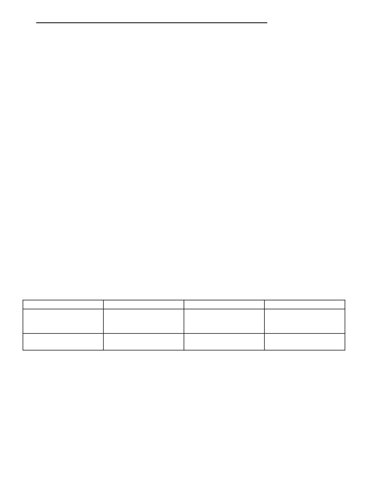
TORQUE CHART
TORQUE SPECIFICATIONS
DESCRIPTION N·m Ft. Lbs. In. Lbs.
Pressure Transformer Unit
For Brake Cables To
Frame Crossmember
25 — 221
Hand Brake Lever To
Seat Frame
25 — 221
VA BRAKES - BASE 5 - 23