INSTALLATION - REAR
NOTE: Route the park brake cable free of tension
and the risk of chafing.
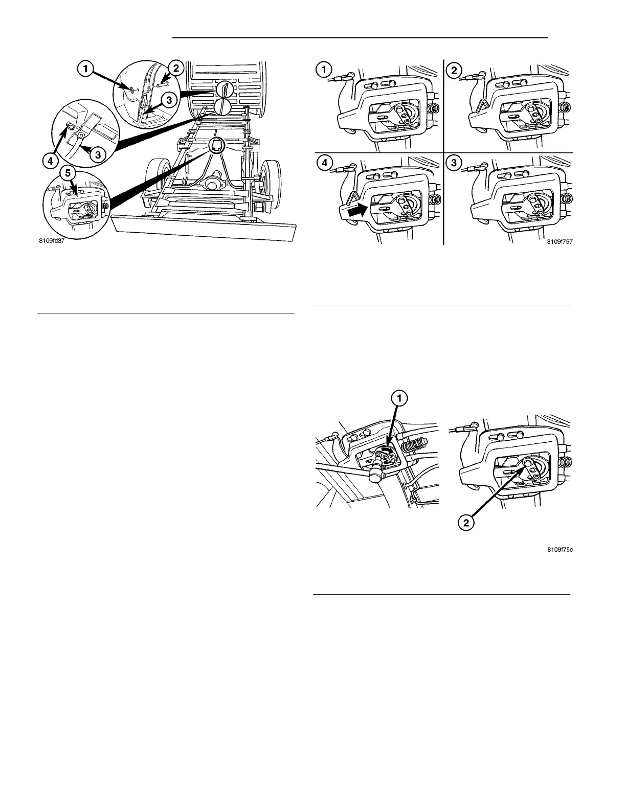
(1) In st all th e ha nd brake cable t o the a nchor
plate (Fig. 31).
(2) In st all the park brake ca ble lock (F ig. 31).
(3) In st all a ll connections on th e h ardwa re cable
(Fig. 31).
(4) In st all the park brake cables to th e shoe (Fig.
31).
(5) In st all the park brake shoes.
(6) In st all the rear wh eels.
(7) Adjust the park bra kes.
(8) Lower th e vehicle.
ADJ U ST M EN T S
ADJUSTMENT - PARKING BRAKE CABLES
(1) Loosen t he bolts of the mountin g brackets (Fig.
33).
(2) In sert a drill bit or an allen wrench with a 6
mm dia meter between th e mou nting bra cket and
front lever (Fig. 33).
(3) Push th e mount ing bracket back until the fron t
brake cable is fr ee of play and wit hout ten sion (Fig.
33).
(4) Tighten th e bolts to t he m ounting bra cket
Tighten t o 25 N·m (221 in. lbs.) (Fig. 33).
(5) Remove the 6 mm diameter drill bit or allen
wrench (Fig. 33).
(6) Tighten the h and bra ke lever one notch (F ig.
33).
(7) Clam p the eccen tric clockwise un til the wheels/
disc br ake rotors ca n st ill be turn ed with th e for ce of
the h and (Fig. 34).
(8) Tighten t he cla mp bolt (F ig. 34).
(9) Relea se the han d brake lever.
(10) Check the wheel for free movem ent.
LEV ER
REMOVAL
(1) Disconn ect t he fron t br ake cable from the pul-
ley unit.
(2) Remove the front bra ke cable from t he ha nd
brake lever (F ig. 29).
(3) Remove the circle cover (Fig. 35).
Fig. 32 FRONT PARK BRAKE CABLE
1 - RETAINING CLIP
2 - LOCKING PIN
3 - FRONT PARK BRAKE CABLE
4 - RETAINING CLIP
5 - PARK BRAKE CABLE ADJUSTER
Fig. 33 PARK BRAKE ADJUSTER
1 - LOOSEN MOUNTING BOLTS
2 - 6 mm ALLEN WRENCH
3 - MOUNTING BOLTS TIGHTENED
4 - FREEPLAY WITH NO TENSION
Fig. 34 PARK BRAKE ADJUSTMENT
1 - ECCENTRIC CLOCKWISE
2 - CLAMP SCREW TIGHTENED
5-26 BRAKES-BASE VA