(4) Remove t he bolts on the ha nd br ake lever (F ig.
35).
(5) Pull th e cover off the h and brake lever (Fig.
35).
(6) Disconn ect t he hand bra ke check switch and
wiring har ness from th e hand brake lever (Fig. 35).
(7) Remove the hand br ake lever (Fig. 35).
INSTALLATION
(1) In st all the han d brake lever (F ig. 35).
(2) Reconnect the hand bra ke check switch and the
wiring har ness to t he ha nd bra ke lever (Fig. 35).
(3) In st all the cover to the han d brake lever (Fig.
35).
(4) In st all the bolt s on the h and br ake lever.
Tighten t o 25 N·m (221 in. lbs.) (Fig. 35).
(5) In st all the circle cover (Fig. 35).
(6) In st all th e fron t br ake cable t o th e ha nd brake
leve r.
(7) Connect the front brake cable to the pulley u nit
(Fig. 35).
SH OES
REM OVAL
REMOVAL - (SRW)
(1) Raise and support the vehicle.
(2) Remove the rear wheels.
(3) Remove the disc bra ke r otor.
(4) Disconn ect th e front park brake cable from the
pulley u nit. Do not remove the rear park brake
cables.
(5) Remove the r etra cting springs using specia l
tool 9280 (Fig. 36).
(6) Remove the adj u st er (Fig. 36).
(7) Remove the pressu re sprin gs using special tool
9281 (Fig. 36).
(8) Remove the rear park brake shoes (F ig. 36).
Pull the park brake shoes apart at the bottom
and remove them together with the adjuster.
REMOVAL - (DRW)
(1) Raise and support the vehicle.
(2) Remove the rear wheels.
(3) Remove the wheel fla nge r ing.
(4) Remove the disc bra ke r otor.
(5) Disconn ect th e front park brake cable from the
pulley u nit. Do not remove the rear park brake
cables.
(6) Remove the retr acting springs (F ig. 37).
(7) Remove the adj u st er (Fig. 37).
(8) Remove the pressure spr ings (Fig. 37). by
depr essing wit h your fin gers a nd twistin g.
(9) Remove the rear park brake shoes (F ig. 37).
Pull the park brake shoes apart at the bottom
and remove them together with the adjuster.
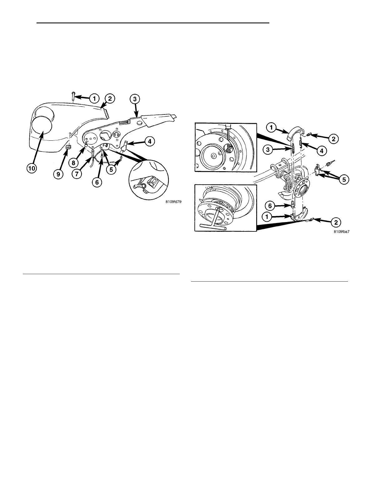
Fig. 35 HAND BRAKE LEVER
1 - LOCKING PIN
2 - COVER
3 - HAND BRAKE LEVER
4 - HAND BRAKE CHECK SWITCH
5 - WIRING HARNESS
6 - BOLT
7 - HAND BRAKE CABLE
8 - BOLT
9 - RETAINING CLIP
10 - CIRCLE COVER
Fig. 36 PARK BRAKE SHOES
1 - PARK BRAKE SHOES
2 - PRESSURE SPRING
3 - RETRACTING SPRING (SHORT HOOK EYE)
4 - RETRACTING SPRING (LONG HOOK EYE)
5 - CABLE LOCK
6 - ADJUSTER
VA BRAKES - BASE 5 - 27