(1) Disconn ect the n egat ive battery cable.
(2) Drain the cooling system.
(3) Record th e location an d sn ip the wire ties.
(4) Unscr ew t he engine block heater from the core
plug hole and r emove (Fig. 6).
INSTALLATION
(1) Scr ew the block heater into the core hole (F ig.
6).
(2) Route t he heater wiring harn ess a way from
and inter ference and secu re with wir ing tie stra ps.
(3) Refill th e cooling system.
(4) Connect the n egat ive batt ery cable.
(5) St art th e engine and inspect for lea ks.
EN GI N E COOLAN T T EM P SEN -
SOR
DESCRIPTION
The ECM det ermines th e oper ating t empera ture of
the engine by using th e signal fr om t he coolant tem-
perat ure sen sor. The coolan t temper atur e sensor ha s
a negative temper atur e coefficient (NTC) r esistor
contained in th e pla st ic housing. NTC mea ns; the
higher the tempera ture, th en the lower th e resis-
tance. The E CM also uses the coolan t temperatur e
sensor signal to calcula te glow plu g relay triggering.
If t he coola nt temper ature sensor fails during oper a-
tion, the ECM will switch on the cooling fan to pr e-
vent engine overhea tin g (A/C models only).
REMOVAL
WARNING: Risk of injury to skin and eyes from
scalding with hot coolant. Risk of poisoning from
swallowing coolant. Do not open cooling system
unless coolant temperature is below 90°C. Open
cap slowly to release pressure. Store coolant in
suitable and appropriately marked container. Wear
protective gloves, clothes and eye wear.
(1) Disconn ect nega tive battery cable.
(2) Remove engine cover (Refer to9-ENGINE-
REMOVAL).
(3) Partailly drain coolant system (Refer to 7 -
COOLING/ENGINE/COOLANT - STANDARD PRO-
CEDURE).
(4) Unplug coolan t t empera tur e sensor electrical
connect or.
NOTE: Capture any residual coolant that may flow.
(5) Remove coola nt temper atur e sensor (Fig. 7).
INSTALLATION
WARNING: Risk of injury to skin and eyes from
scalding with hot coolant. Risk of poisoning from
swallowing coolant. Do not open cooling system
unless coolant temperature is below 90°C (194°F).
Open cap slowly to release pressure. store coolant
in suitable and appropriately marked container.
Wear protective gloves, clothes and eye wear.
(1) Position and inst all coolant tem perature sensor
(Fig. 7).
(2) Connect coola nt temperatur e sen sor elect rical
connect or (Fig. 7).
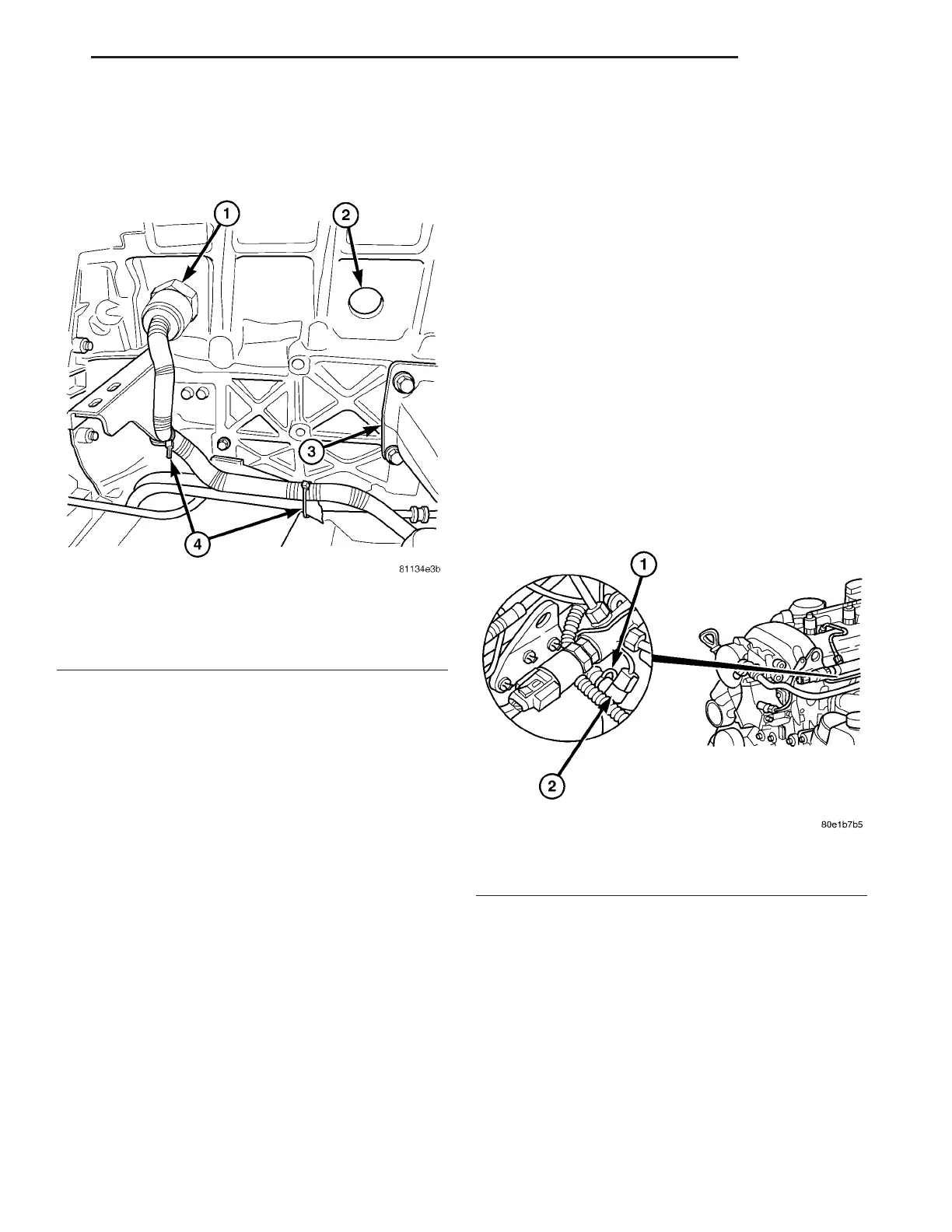
Fig. 6 ENGINE BLOCK HEATER
1 - ENGINE BLOCK HEATER
2 - CORE PLUG
3 - ENGINE MOUNT
4 - WIRING TIE STRAPS
Fig. 7 ENGINE COOLANT TEMPERATURE SENSOR
1 - RETAINING CLAMP
2 - ENGINE COOLANT TEMPERATURE SENSOR
VA ENGINE 7 - 15