(17) Take off ch arge air cooler togeth er with cool-
ing loop of t he steerin g at the ra diator (F ig. 10).
(18) Remove bottom radiator trim (Fig. 10).
(19) Deta ch coolant hose at ra diator.
(20) Deta ch coolant pipe toget her with cool a nt
hose at t he fan shroud.
(21) Remove ra diator fan sh roud (Fig. 10).
INSTALLATION
(1) In st all fan shroud to radiat or (Fig. 10).
(2) Attach coolant pipe wit h hoses to fan shr oud
(Fig. 10).
(3) Attach coolant h ose at radiator (Fig. 10).
(4) In st all bottom radia tor trim (Fig. 10).
(5) In st all charge a ir cooler along wit h cooling loop
of the power steer ing, to r adiator (Fig. 10).
(6) In st all radiator assembly int o the r ubber grom -
mets (F ig. 9).
(7) In st all bot h right and left side r adiator trim
pa nels (F ig. 9).
(8) Attach the transmission cooler lines (F ig. 9).
(9) Attach coolant hose to th e bottom right of the
radiator (Fig. 9).
(10) Atta ch both power steerin g hydra ulic lines
(Fig. 9).
(11) Connect coolant level sensor electr ical connec-
tor (Fig. 9).
(12) Connect coolant hoses t o the coolant reservoir,
radiator and water pump (Fig. 9).
(13) Atta ch air inta ke pipe at th e body.
(14) Atta ch charge air hose at air in take.
(15) Atta ch charge air hose at turboch arger.
(16) Install A/C con denser.
(17) Install front bumper.
(18) Install front end cross mem ber.
(19) Refill power st eering t o proper level.
(20) Refill t ransm ission to proper level.
(21) Close radiator drain plu g and refill th e cooling
system (Refer t o 7 - COOLING/ENGINE/COOLANT -
STANDARD PROCE DURE ).
(22) Recha rge a ir con dition ing (Refer to 24 -
HEATING & AIR CONDITIONING/PLUMBING -
STANDARD PROCE DURE ).
(23) Run engine u ntil wa rm and ch eck for leaks.
RADI AT OR PRESSU RE CAP
DESCRIPTION
All vehicles are equipped with a pressure cap (Fig.
11). This cap releases pr essu re at som e point with in
a range of 124-145 kPa (18-21 psi). The pressure
relief point (in poun ds) is engr aved on top of th e cap
The cooling system will opera te a t pressur es
slightly above atmospher ic pressur e. This resu lts in a
higher coolan t boilin g point allowing increased r adi-
ator cooling capacity. The cap conta ins a spring-
loaded pressure relief valve. This valve opens when
system pr essu re reaches the release r ange of 124-145
kPa (18-21 psi).
A rubber gasket seals the radiator filler neck. This
is don e to mainta in vacuum du ring coola nt cool-down
and to prevent leakage when system is under pres-
sure.
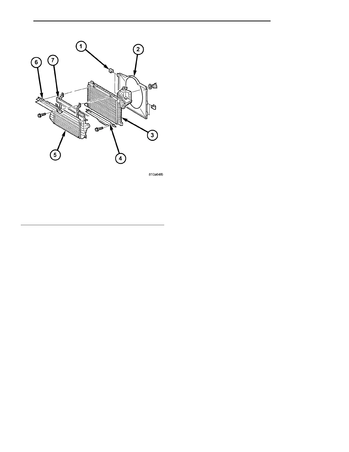
Fig. 10 RADIATOR AND FAN SHROUD
1 - CLIP
2 - SHROUD
3 - RADIATOR
4 - BOTTOM RADIATOR TRIM PANEL
5 - CHARGE AIR COOLER
6 - TOP RADIATOR TRIM PANEL
7 - POWER STEERING COOLER LOOP
VA ENGINE 7 - 19