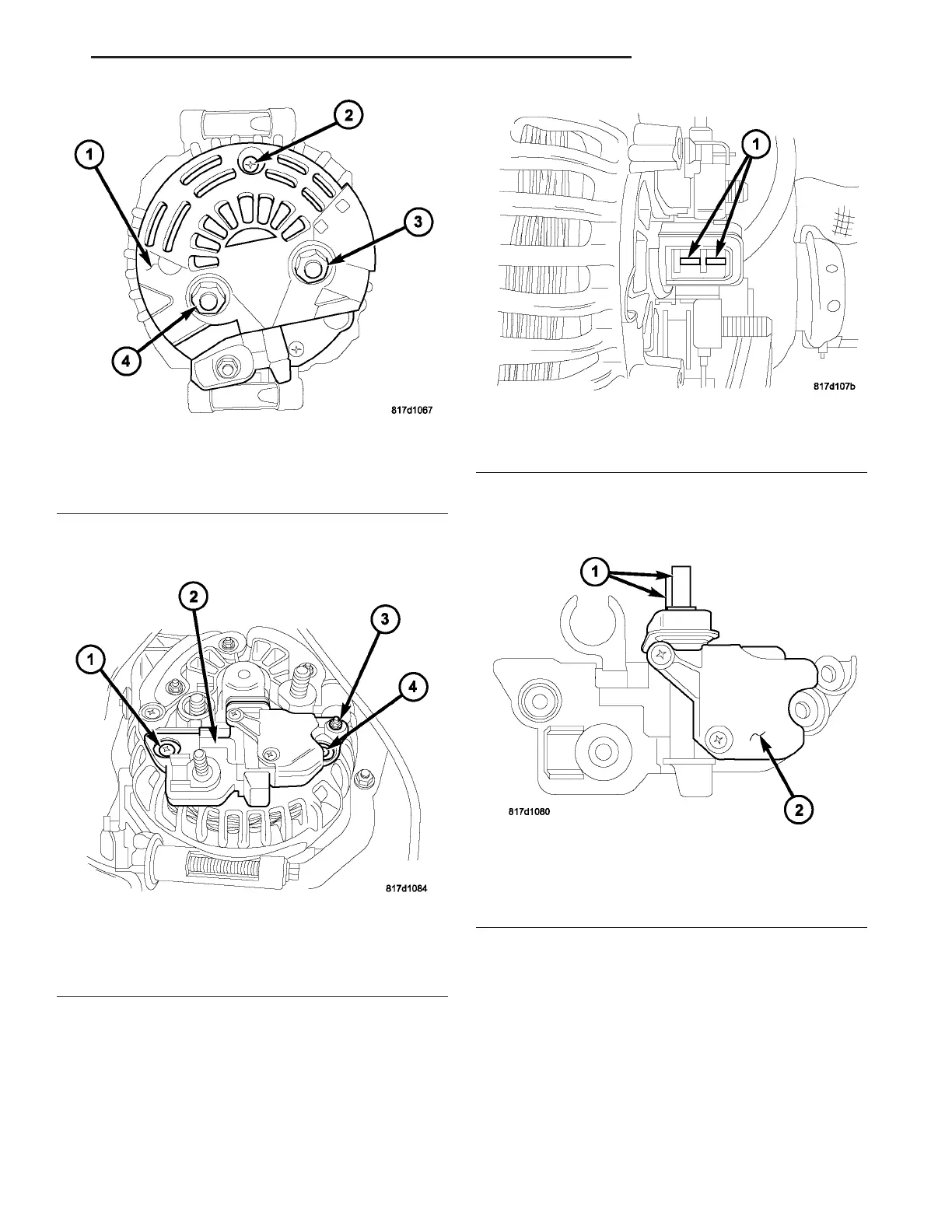
(7) Remove plastic cover (1) (Fig. 18) by removing
scr ew (2) a nd nut s (3) and (4).
(8) Remove screws (1), (3), an d (4) (Fig. 19).
(9) Remove voltage regulator (2) (Fig. 19). To p r e -
vent damage to the carbon brushes, slowly pull
the voltage regulator straight out from genera-
tor w ithout slanting or tipping.
(10) Check condition of com mutator r ings (1) (Fig.
20). If rings are worn, repla ce gen erat or assembly.
(11) Check condit ion of carbon bru sh es (1) (Fig.
21). If br ushes ar e worn, repla ce generator assembly.
Fig. 18 PLASTIC COVER
1 - Plastic Cover
2 - Screw
3 - Nut
4 - Nut
Fig. 19 MOUNTING BOLTS
1 - Screw
2 - Voltage Regulator
3 - Screw
4 - Screw
Fig. 20 COMMUTATOR RINGS
1 - Commutator Rings
Fig. 21 VOLTAGE REGULATOR
1 - Carbon Brushes
2 - Voltage Regulator
VA CHARGING SYSTEM 8F - 25