INSTALLATION
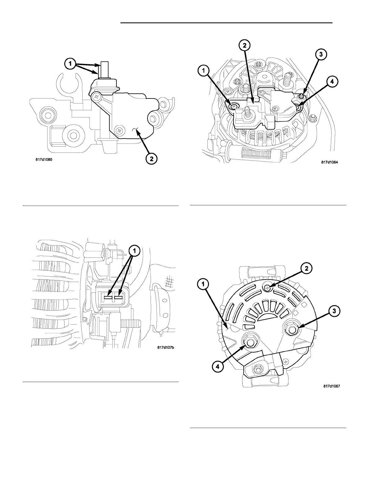
(1) Check con dition of car bon brushes (1) (Fig. 22).
If brushes a re worn, replace gener ator assembly.
(2) Check condition of commut ator rings (1) (Fig.
23). If rings are worn, repla ce gen erat or assembly.
(3) Position volta ge r egulat or (2) (Fig. 24) t o r ear
of genera tor. To p r e v e n t d a m a g e t o t h e c a rb o n
brushes (1) (Fig. 22), slow ly install the voltage
re gu lato r s traig ht in to th e g en era tor with ou t
slanting or tipping.
(4) In st all screws (1), (3), an d (4) (Fig. 24).
(5) In st all plastic cover (1) (Fig. 25), screw (2) an d
nuts (3) and (4).
Fig. 22 VOLTAGE REGULATOR
1 - Carbon Brushes
2 - Voltage Regulator
Fig. 23 COMMUTATOR RINGS
1 - Commutator Rings
Fig. 24 MOUNTING BOLTS
1 - Screw
2 - Voltage Regulator
3 - Screw
4 - Screw
Fig. 25 PLASTIC COVER
1 - Plastic Cover
2 - Screw
3 - Nut
4 - Nut
8F - 26 CHARGING SYSTEM VA