DEFOGGER SWI T CH CON N ECT OR PI N
CALL-OU T
PIN FUNCTION
1 FUSED B+ (DRL RELAY)
3 IGNITION SWITCH OUTPUT (START-
RUN)
5 PANEL LAMPS DRIVER
7 DEFOGGER SWITCH OUTPUT
9 PANEL LAMPS DRIVER
10 GROUND
REMOVAL
WARNING: To avoid personal injury or death, on
vehicles equipped with airbags, disable the supple-
mental restraint system before attempting any
steering wheel, steering column, airbag, seat belt
tensioner, or instrument panel component diagno-
sis or service. Disconnect and isolate the battery
negative (ground) cable, then wait two minutes for
the system capacitor to discharge before perform-
ing further diagnosis or service. This is the only
sure way to disable the supplemental restraint sys-
tem. Failure to take the proper precautions could
result in accidental airbag deployment.
(1) Disconn ect and isolate the negat ive ba tter y
cable.
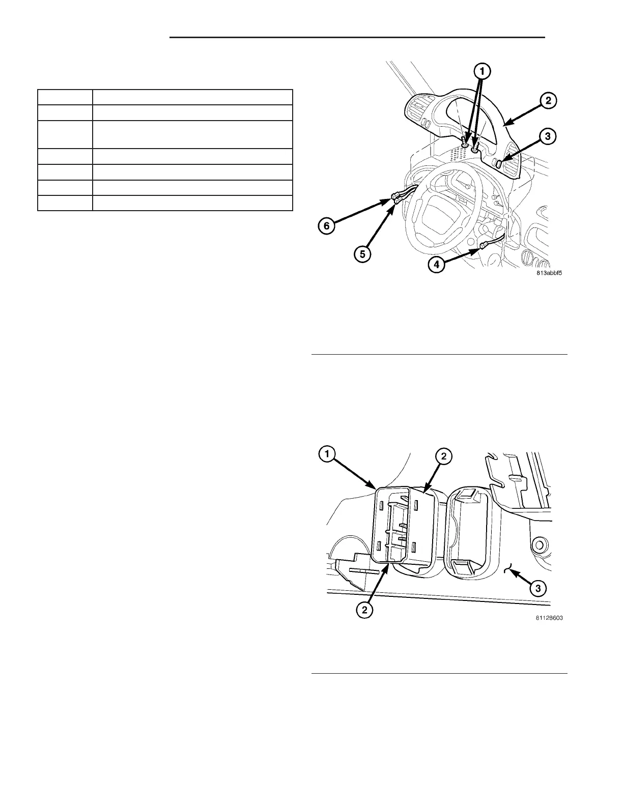
(2) Remove the cluster bezel from t he in st rumen t
pa nel (Fig. 7) (Refer to 23 - BODY/INSTRUMENT
PANEL/CLUSTER BEZEL - RE MOVAL).
(3) From th e back of th e cluster bezel, squeeze the
two la tches on th e rear window defogger switch body
and pu sh th e switch out th rough the face of t he bezel
(Fig. 8).
(4) Remove th e rear win dow defogger switch from
the cluster bezel.
INSTALLATION
(1) Position the rea r win dow defogger swit ch to t he
pr oper mounting hole on the fa ce of the clu st er bezel.
(2) Usin g ha nd pressure, push the rear window
defogger switch firm ly a nd evenly into the swit ch
Fig. 7 Cluster Bezel Remove/Install
1 - SCREWS (2)
2 - CLUSTER BEZEL
3 - REAR WINDOW DEFOGGER SWITCH
4 - DEFOGGER SWITCH CONNECTOR
5 - WIRE HARNESS CONNECTOR
6 - WIRE HARNESS CONNECTOR
Fig. 8 Headlamp Leveling Switch Remove/Install
1 - SWITCH
2 - LATCH (2)
3 - CLUSTER BEZEL
8G - 6 H EAT ED GL AS S VA