(5) From the inside of th e vehicle, r emove the four
nuts that secure the t ail lam p u nit hou sing to the
vehicle.
(6) Remove t he tail la mp u nit housin g and gasket
from the outside of th e veh icle.
INSTALLATION
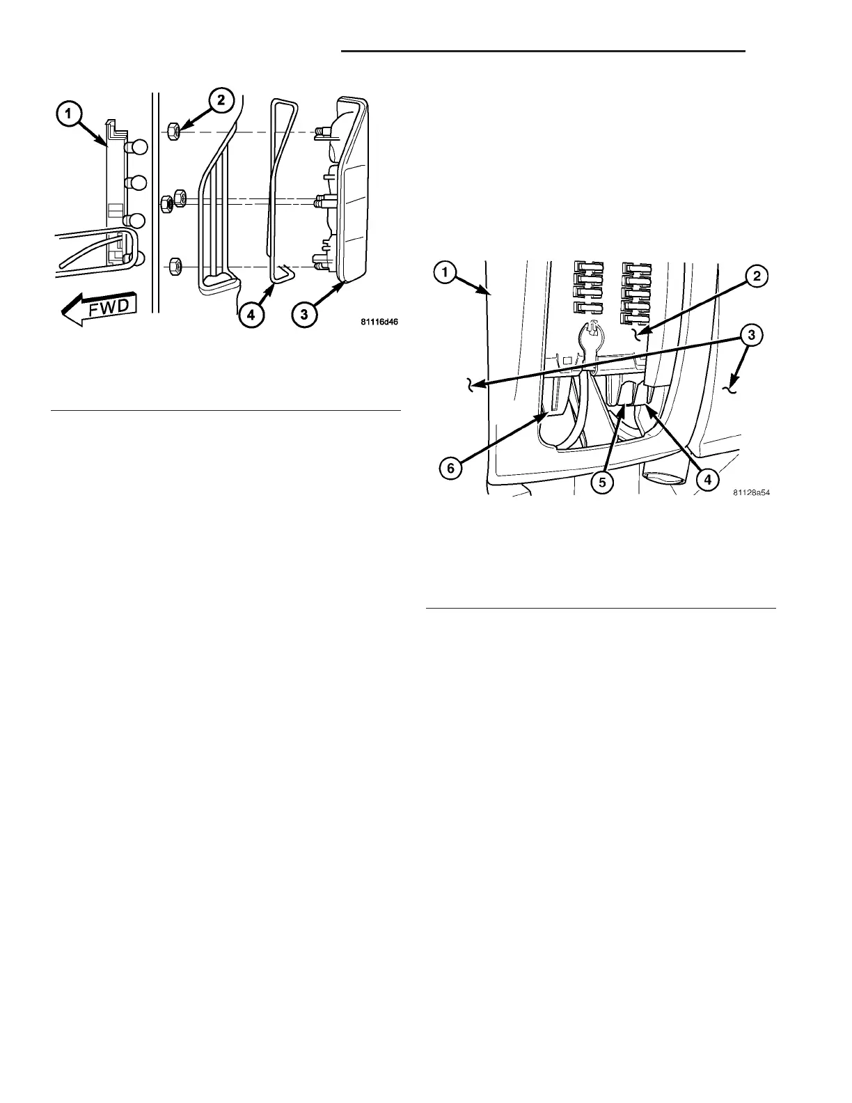
(1) Position the tail lamp u nit hou sing and gasket
to th e outside of th e veh icle (Fig. 48).
(2) From t he inside of th e vehicle, in stall and
tighten th e fou r nu ts th at secu re the tail la mp un it
housin g to the vehicle.
(3) Align the socket pla te with the moun tin g hole
in the inne r re ar p illar.
(4) Usin g han d pressure, push the socket plate
gent ly and even ly into th e inn er rear pillar mou nting
hole until bot h latch tabs ar e fully enga ged.
(5) If t he vehicle is so equ ipped, reinstall th e trim
onto t he inside of the r ight or left rear corner pillar.
(6) Reconnect t he battery negative cable.
TURN SIGNAL RELAY
REMOVAL
WARNING: To avoid personal injury or death, on
vehicles equipped with airbags, disable the supple-
mental restraint system before attempting any
steering wheel, steering column, airbag, seat belt
tensioner, or instrument panel component diagno-
sis or service. Disconnect and isolate the battery
negative (ground) cable, then wait two minutes for
the system capacitor to discharge before perform-
ing further diagnosis or service. This is the only
sure way to disable the supplemental restraint sys-
tem. Failure to take the proper precautions could
result in accidental airbag deployment.
(1) Disconn ect and isolate the battery nega tive
cable.
(2) Remove the fuse access pan el from the st eering
column open ing cover below the st eerin g column on
the instrument panel.
(3) Reach through and below t he inboa rd side of
the fuse access open ing to a ccess the turn signa l
rela y (Fig. 49).
(4) Remove the turn signal relay by gr asping it
firmly, releasing the latch es a nd pulling it straight
down from th e recept acle on the bot tom of the fuse
block.
INSTALLATION
WARNING: To avoid personal injury or death, on
vehicles equipped with airbags, disable the supple-
mental restraint system before attempting any
steering wheel, steering column, airbag, seat belt
tensioner, or instrument panel component diagno-
sis or service. Disconnect and isolate the battery
negative (ground) cable, then wait two minutes for
the system capacitor to discharge before perform-
ing further diagnosis or service. This is the only
sure way to disable the supplemental restraint sys-
tem. Failure to take the proper precautions could
result in accidental airbag deployment.
(1) Position the tur n signa l relay to t he receptacle
on the bottom of t he fuse block (Fig. 49).
(2) Align the turn signa l r elay terminals with the
term inal cavities in the fuse block receptacle.
Fig. 48 Tail Lamp Unit Remove/Install
1 - SOCKET PLATE
2 - NUT (4)
3 - LAMP HOUSING
4 - GASKET
Fig. 49 Turn Signal Relay
1 - STEERING COLUMN OPENING COVER
2 - FUSE BLOCK
3 - LOWER INSTRUMENT PANEL
4 - TURN SIGNAL RELAY
5 - ENGINE CONTROL MODULE RELAY
6 - WIPER RELAY
8L - 26 LAMPS/LIGHTING - EXTERIOR VA