The Z-Drive Assembly
DSX™ System Service Manual 7-19
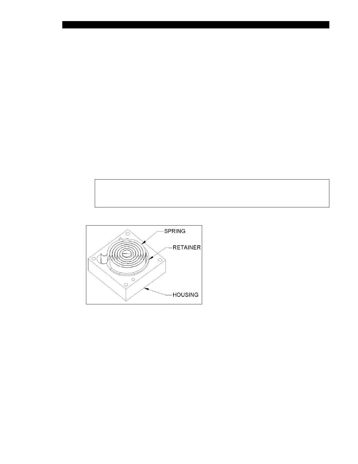
5 Carefully remove the Rotary Spring (Part No. 324600400) and place a new one
on the housing (Part No. 204026700) as shown in Figure 7-17, allowing the
retainer to slide off while pushing the spring into the housing fully. Discard the
retainer.
6 Move the Z drive block to the end of the rail closest to the motor. Ensure it
remains there while winding the spring.
7 Place the spring assembly onto the Z assembly, ensuring that the eye lines up
with the slot in the Z idler shaft and being careful not to push the spring out of the
housing. Orient the housing so that the two screw holes on the side of the
housing are facing towards the end of the Z assembly extrusion.
8 Attach the cover (Part No. 204026800) to the housing using two M3x12 flat head
screws.
9 Rotate the spring assembly eight complete revolutions counter-clockwise (as
observed from the spring assembly). Secure the assembly to the extrusion using
four M3x30 flat head screws.
Note: Ensure that the assembly is square and flush with the extrusion
and that the two tapped holes in the housing are on the bottom when
completed.
Figure 7-17 Insertion of Rotary Spring