The Z-Drive Assembly
7-24 DSX™ System Service Manual
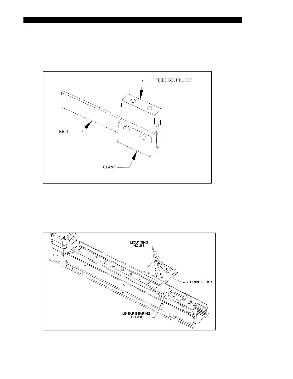
3 Fit the Adjustable Belt Block (Part No. 204003400) and the Belt Clamp (Part No.
204012400) to the idler end of the belt using two M3 x 8 Cap Head Screws and
Loctite 222 (Figure 7-25). Ensure that the belt covers all three teeth in the belt
block.
Figure 7-25 Placing the Adjustable Belt Block on the Idler End of the Drive Belt
4 Place the Adjustable Drive Block and the Fixed Drive Block in position and the
place the Z-Drive block (Part No. 204004600) onto the linear bearing block
(Figure 7-26). Fit the Z-Drive Block to the Linear Bearing Block using the four M3
x 6 Cap Head screws.
Figure 7-26 Z-Drive Block and the Linear Bearing Block