The Z-Drive Assembly
DSX™ System Service Manual 7-25
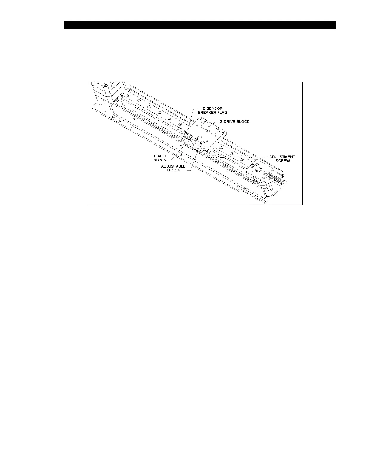
5 Place the Z sensor breaker flag (Part No. 204011300) on to the top of Z-drive
block, attach the Z-drive block to the fixed block with two M3 X 12 cap head
screws and apply Loctite 222 to the tightened screws (Figure 7-27).
Figure 7-27 Mounting the Z Sensor Breaker Flag, Z-Drive Block, and the Linear
Bearing Block
6 Mount the adjustable Belt Block in the slotted holes using two M3 x 12 cap head
screws and two M3 flat washers but do not tighten. Insert one M3 x 30 button Posi
head screw through the adjustable belt block and into the fixed belt block.