The Y-Drive Assembly
7-36 DSX™ System Service Manual
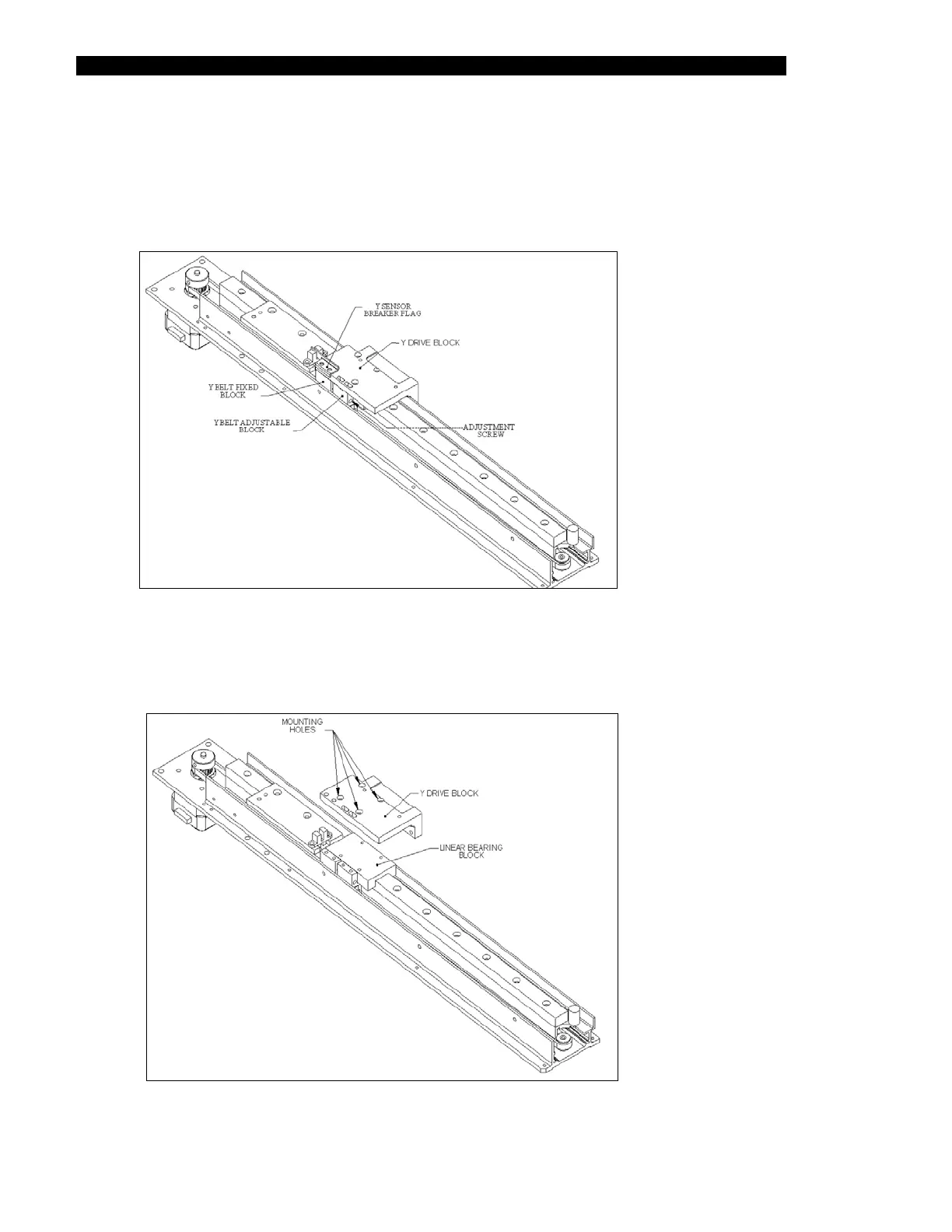
3 Remove the M3 x 30 button Posi head screw (adjustment screw) that connects
the Y Belt Fixed Block and Y Belt Adjustment block. Remove the Y sensor
breaker flag and the Y Belt Fixed Bracket (Figure 7-42) by removing the 2 M3 x
12 Cap head screws and remove the Y adjustable block by removing the two M 3
x 30 Posi screws.
Figure 7-42 Removing the Sensor Flag and Belt Blocks
4 Remove the Y-Drive block from the linear bearing block by removing the four M3
x 6mm cap head screws (Figure 7-43).
Figure 7-43 Removing Y-Drive Block