Removing External Components
9-8 DSX™ System Service Manual
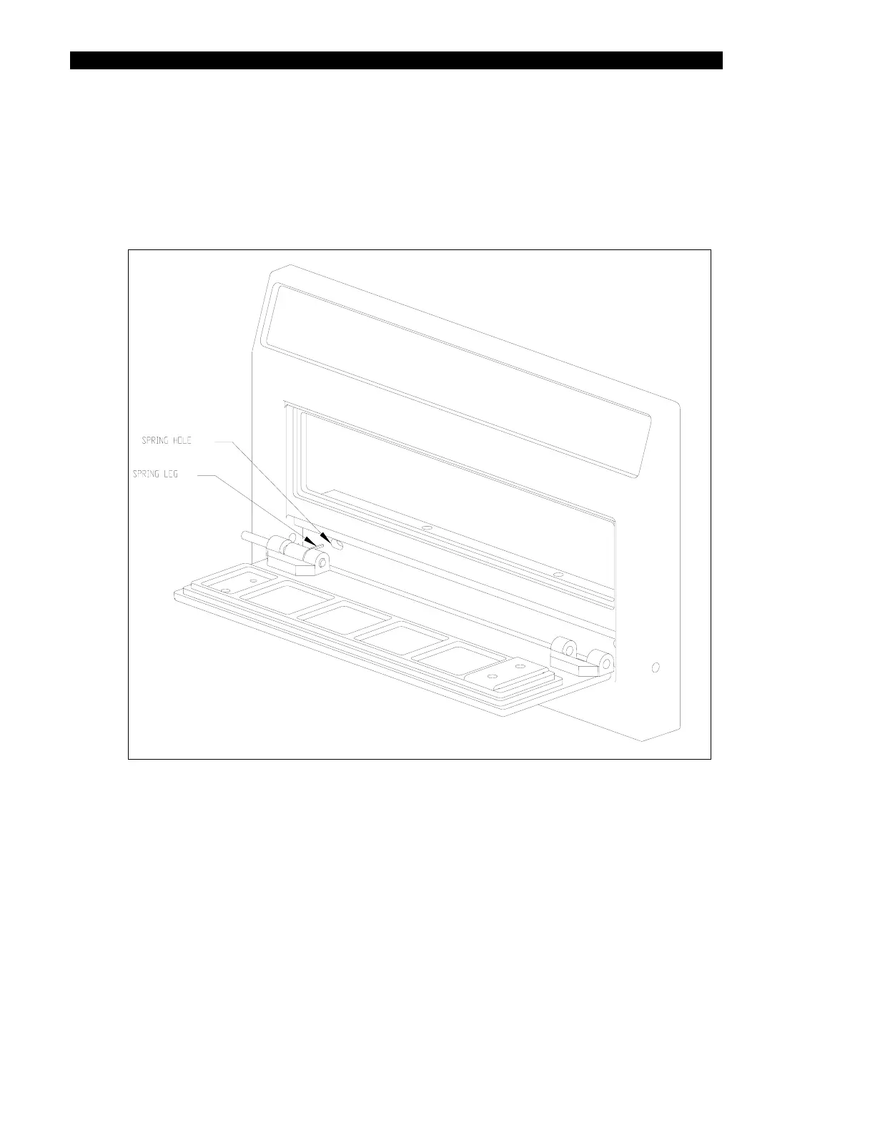
4 Adjust the pins so that one pin is flush and the other is projecting 1/8”. Insert the
projecting pin of the door into the bezel. As you do this, deflect the spring with a
screwdriver so that it is pointing back and will enter the spring recess in the bezel
shown in Figure 9-7. Do this with both springs. Insert the other end of the door.
Engage the pin by pressing with a screwdriver. Use a miniature friction lock quick-
grip clamp to press in the pins into the bezel.
Figure 9-7 Position of Spring Hole and Leg
If needed, use a 2mm Allen wrench to align the pin with bezel pinhole until the pin is started.
Test the door by opening it and then letting go 5 times. The door should shut by itself. If it
does not shut properly, use a 3mm Allen wrench to push out the pins and begin the
installation procedure again.