Repairing/Replacing Internal Components
9-18 DSX™ System Service Manual
4 Remove the pulley assembly from motor shaft by loosening the setscrew and then
remove the two socket head cap screws that fasten the motor to the mount.
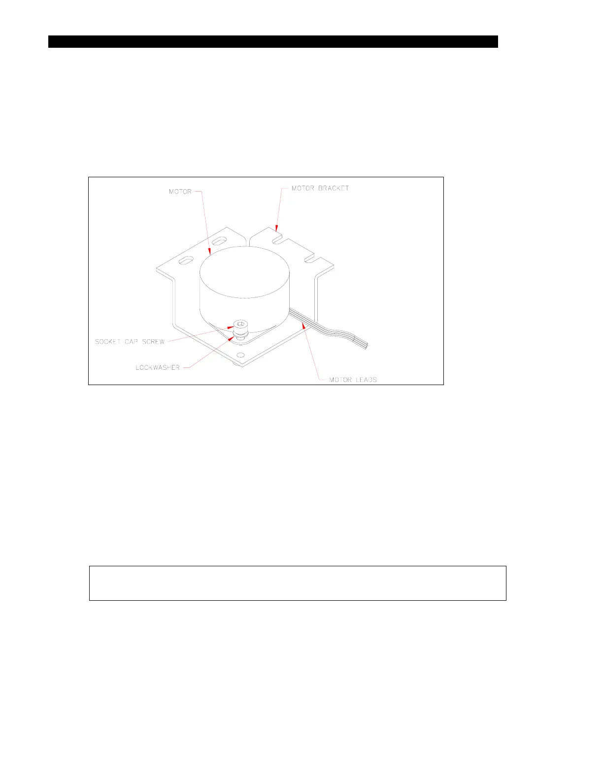
5 Remove the Motor (Part No. 15000440) from the motor mount (Part No.
220000760) by removing the two M3 x 6mm socket head screws and M3 Lock
Washers (Figure 9-18).
Figure 9-18 Motor and Mount
6 When you replace the pulley on the new motor, secure the setscrew with
Loctite 242
7 Place the pulley on the motor shaft (Figure 11-13). Set the position of the pulley
using the pulley gauge P/N AMFIX002. Fasten the pulley using the setscrew and
Loctite #242.
8 Rewrap the belt around the motor pulley. Loosely fasten the motor to the chassis
using 4 M3 x 6mm socket head cap screws, M3 flat washers, and M3 lock
washers. Route the wire from the motor to the right in the back. Apply 7 in-lbs of
torque to tighten the screws.
Note: When tightening the screws, use torque driver SN160 to tighten the
screws to 7 in-lbs.