Repairing/Replacing Internal Components
DSX™ System Service Manual 11-47
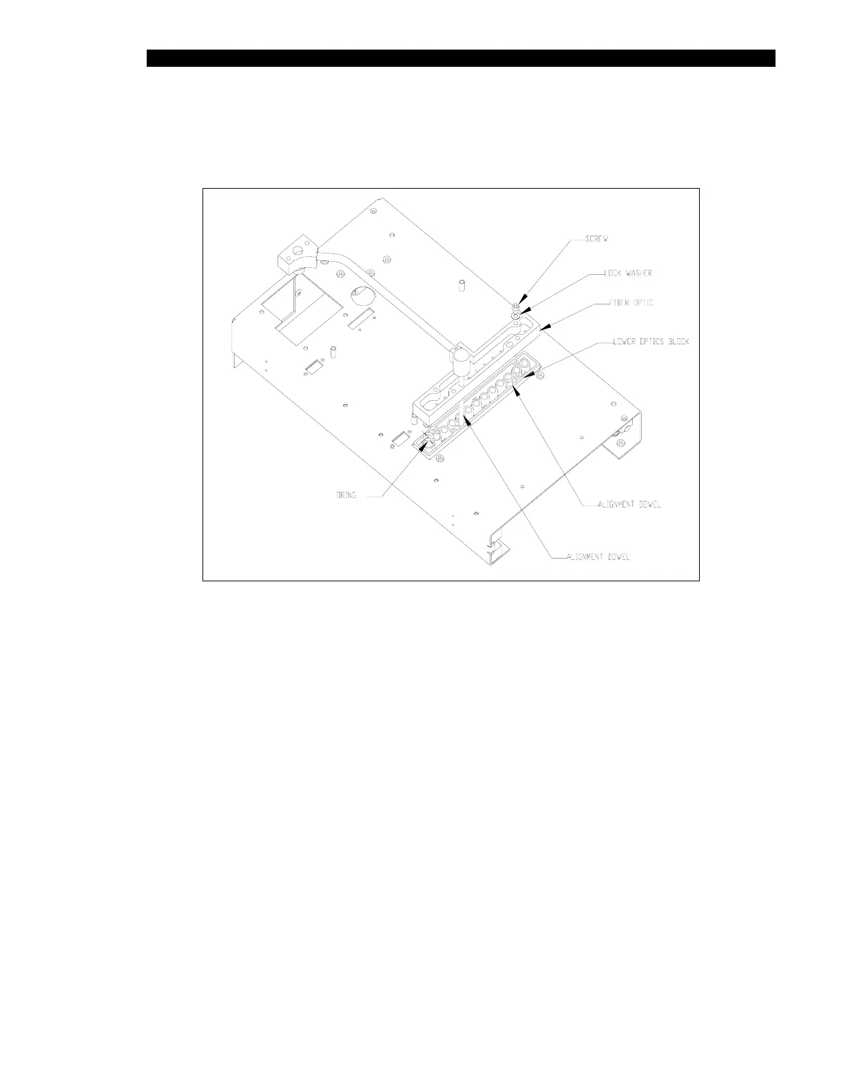
8 Insert 4mm alignment pins
(AMFIX004) into the alignment holes. Fasten the block
with four M3 x 20mm socket head caps screws and M3 lock washers
(Figure 11-43).
Figure 11-43 Alignment of the Lens Assembly
9 Place the optics alignment jig (AMFIX003) into the plate carrier.
10 Insert the M4 alignment pins (AMFIX004) through the upper optics, the jig and the
bottom optics.